Eaton VSR Series Instructions Manual Download Page 22

For more information visit: www.eaton.com

www.eaton.com

www.eaton.com

www.eaton.com

www.eaton.com

Instructions for
VSR-Series Type 5HK
Vacuum Motor Starter

IB01301027E

IB01301027E

Page  20

Page  20

Page  20

Page  20

Page  20

Effective:  May 2008

Effective:  May 2008

Effective:  May 2008

Effective:  May 2008

Effective:  May 2008

SECTION 6:  INSPECTION AND MAINTENANCE

ALL WORK PERFORMED ON THIS STARTER SHOULD BE DONE
WITH THE MAIN DISCONNECT DEVICE OPEN AND LOCKED OUT.
AS WITH ANY  STARTER  OF THIS VOLTAGE, THERE  IS  DANGER
OF ELECTROCUTION AND/OR SEVERE BURNS. MAKE CERTAIN
THAT POWER IS OFF. CHECK FOR VOLTAGE WITH VOLTAGE
SENSOR OR A METER OF THE APPROPRIATE RANGE. MAKE
CERTAIN THAT ALL TRANSFORMERS ARE  ISOLATED TO
PREVENT FEEDBACK AND THE RESULTANT GENERATION OF
HIGH VOLTAGE.

The starter should be serviced on a regular basis. The time interval
between maintenance checks is variable and dependant on factors
such as environment, duty cycle, etc. Unless the experience of the
maintenance personnel suggests a different service interval, the
contactor should go through a checkout after each 50,000
operations or annually, which ever occurs first.
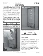
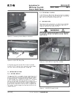
6.1  GENERAL

The starter should be kept clean and free from dust and other
accumulated deposits. Dust can be removed from the starter by
wiping with a lint free cloth.

Inspect for loose joints that produce excess heat and discolor
conductors. Verify that insulation has not been damaged by high
temperatures. Do not over-torque bolts while verifying tightness.
Hardware is both Metric and US standard sizes. Refer to Table 

6.1

for recommended torque values.

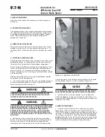
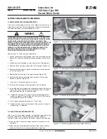
6.2  VACUUM INTEGRITY CHECK

THIS PROCEDURE REQUIRES THE USE OF A HIGH POTENTIAL
TEST  UNIT WHICH  PRODUCES  HAZARDOUS VOLTAGES.

APPLYING HIGH VOLTAGES ACROSS THE OPEN CONTACTS
OF A VACUUM INTERRUPTER MAY PRODUCE X-RAYS. THE
RADIATION MAY INCREASE WITH AN INCREASE IN THE VOLT-
AGE OR A DECREASE IN THE DISTANCE BETWEEN THE OPEN
CONTACTS. THE LEVELS OF RADIATION GENERATED AT THE
RECOMMENDED TEST VOLTAGES AND  NORMAL  CONTACTOR
OPEN GAP SPACING ARE EXTREMELY LOW. HOWEVER, AS A
PRECAUTIONARY MEASURE IT IS RECOMMENDED THAT ALL
OPERATING PERSONNEL STAND AT LEAST THREE FEET AWAY
FROM THE  CONTACTOR WHILE  PERFORMING THIS TEST.

Vacuum starters depend on the vacuum in each interrupter to
successfully stop current flow to the connected load when the
starter opens.

WARNING

WARNING

WARNING

Starters are thoroughly tested at the factory prior to shipment. They
can, however, be damaged by improper handling during shipment
and storage. The integrity of the vacuum interrupters should
therefore be verified before the contactor is energized for the first
time. The check should also be made each time the contactor is
serviced or repaired, otherwise the test should be performed each
50,000 operations or annually, whichever occurs first.

To verify the integrity of the vacuum interrupters a voltage of
19kV-ac should be applied across the open contacts of the
interrupters. The voltage should be applied for 60 seconds without
breakdown. Breakdown is defined as a current of 5mA or more
flowing across the open contacts. Note that approximately 1mA of
current will flow through each interrupter during the AC test due to
the capacitance of the vacuum interrupter.

If a DC high potential test unit is used, make certain that the peak
voltage does not exceed 28kV, the peak of the corresponding AC
RMS test voltage. A megger cannot be used to verify vacuum
integrity due to its limited output voltage.

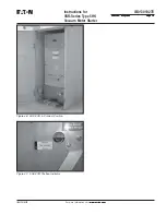
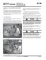
6.3  INTERRUPTING WEAR CHECK

The interrupters used in the starter are designed for long electrical
life. Replacement should be at 300,000 operations except in cases

r

e

t

e

m

a

i

D

)

m

m

(

e

u

q

r

o

T

m

-

N

e

z

i

S

t

l

o

B

.

n

i

-

b

l

4

1

.

3

-

8

.

2

2

3

-

8

4

2

5

2

.

6

-

6

.

5

2

3

-

0

1

6

3

6

4

.

0

1

-

4

.

9

0

2

-

5

2

.

2

7

8

4

.

5

2

-

9

.

2

2

8

1

-

1

3

.

4

4

1

0

1

6

.

0

5

-

5

.

5

4

6

1

-

8

3

.

0

0

3

2

1

0

.

8

8

-

2

.

9

7

3

1

-

0

5

.

0

4

5

d

e

i

f

i

c

e

p

s

e

s

i

w

r

e

h

t

o

s

s

e

l

n

u

*

Table 6.1  -  Recommended Torque Values*

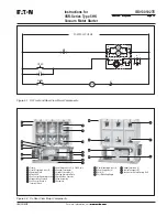
Figure 6-1  Interrupter Wear Check

Summary of Contents for VSR Series

Page 1: ...it www eaton com www eaton com www eaton com www eaton com www eaton com IB01301027E IB01301027E Instructions for VSR Series Breaker To Vacuum Starter Replacement For Type 5HK Breakers 5HK VSR Vacuum...

Page 2: ......

Page 3: ...NSAS THEYMAYBEAPPLIEDTOTHISTYPEOFEQUIPMENTMUSTBE STRICTLYADHEREDTO THESEVACUUMMOTORSTARTERREPLACEMENTSAREDESIGNEDTO BEINSTALLEDPURSUANTTOTHENATIONALELECTRICALCODE NEC SERIOUSINJURY INCLUDINGDEATH CANR...

Page 4: ...13 4 5 INTERRUPTERWEARCHECK 13 4 6 PRIMARYCIRCUITRESISTANCE 13 4 7 ELECTRICALOPERATIONSCHECK 13 4 8 INSERTIONPROCEDURE 13 4 9 REMOVALPROCEDURE 15 SECTION5 DESCRIPTIONANDOPERATION 1 6 5 1 CONTACTOROPE...

Page 5: ...2008 Effective May 2008 Effective May 2008 IB01301027E Tables T able1 1 5HK VSRVacuumMotorStarterReplacementUnitAvailabilityandInterchangeability 5 T able1 2 5HK VSRVacuumMotorStarterReplacementUnitDi...

Page 6: ...nts 17 Figure 5 2 SL Rear View Major Components 17 Figure 5 3 SL Contactors Assembly 18 Figure 5 4 Secondary Contact Block of 5HK VSR 19 Figure 5 5 5HK VSR Code Plate 19 Figure 5 6 5HK VSR Cell Code P...

Page 7: ...ratings are inter changeable with each other 1 1 AVAILABLE5HK VSRMOTORSTARTERREPLACEMENTS Refer to Table 1 1 SATISFACTORYPERFORMANCEOFTHESEVACUUMMOTORSTARTER REPLACEMENTUNITSISCONTIGENTUPONPROPERAPPL...

Page 8: ...01027E Page 6 Page 6 Page 6 Page 6 Page 6 Effective May 2008 Effective May 2008 Effective May 2008 Effective May 2008 Effective May 2008 T able1 2 5HK VSRVacuumMotorStarterReplacementUnitDimensionsinI...

Page 9: ...y y y y y Alwaysremovethestarterfromtheenclosurebefore performinganymaintenance Failuretodosocouldresult inelectricalshockleadingtodeath severepersonnelinjury orpropertydamage y y y y y Proper persona...

Page 10: ...g Dolly Optional item used to help maneuver starter when out of structure Contact Wear Gauge Optional item used to check contact wear Style 5259C11H01 Lifting Sling Optional item used to lift the star...

Page 11: ...s should be arranged to permit free circulation of air on all sides and temporary heaters should be used to minimize condensation Moisture can cause rusting of metal parts and deterioration of high vo...

Page 12: ...ter IB01301027E IB01301027E Page 10 Page 10 Page 10 Page 10 Page 10 Effective May 2008 Effective May 2008 Effective May 2008 Effective May 2008 Effective May 2008 Figure 3 3 Front External View of 5HK...

Page 13: ...5HK Vacuum Motor Starter IB01301027E Page 11 Page 11 Page 11 Page 11 Page 11 Effective May 2008 Effective May 2008 Effective May 2008 Effective May 2008 Effective May 2008 IB01301027E Figure 3 4 Rear...

Page 14: ...he starter for any damage that occurred during shipment storage and installation Set the dip switches in the coil control board for the proper control voltage and dropout time Figures 4 1 and 4 2 and...

Page 15: ...bolted in position as shown in Figures 3 3 and 3 4 before inserting the starter into the cell EXAMINE THE INSIDE OF THE CELL BEFORE INSERTING THE STARTER FOR EXCESSIVE DIRT OR ANYTHINGTHAT MIGHT INTER...

Page 16: ...ce by the levering arms resting completely against the positive stops located on the starter truck This is the fully connected position Figure 4 6 The position indicator on the starter will show TEST...

Page 17: ...m Instructions for VSR Series Type 5HK Vacuum Motor Starter IB01301027E Page 15 Page 15 Page 15 Page 15 Page 15 Effective May 2008 Effective May 2008 Effective May 2008 Effective May 2008 Effective Ma...

Page 18: ...M coils establish a magnetic field within the interrupter during fault conditions The field disperses the arc during fault current interruption allowing the contactor to interrupt a very high fault c...

Page 19: ...3 Moving Armature Plate Optional Aux Contacts Stop Assembly Baseplate 8 9 10 11 12 13 14 Frame Front Mounting Holes 4 Operating Plate Main Shaft Aux Contact Operating Lever Standard Aux Contacts Coil...

Page 20: ...nt are recessed to prevent accidental short circuiting of the control circuits These secondary disconnects mate in both the operating and test positions No special jumper is required Mechanical stops...

Page 21: ...H MOC SWITCH Figure 5 4 Secondary Contact Block of 5HK VSR Figure 5 5 5HK VSR Code Plate WARNING Figure 5 7 5HK VSR Ground Contact existing levering system located in the existing HK assembly structur...

Page 22: ...NCE BETWEENTHE OPEN CONTACTS THE LEVELS OF RADIATION GENERATED AT THE RECOMMENDED TEST VOLTAGES AND NORMAL CONTACTOR OPEN GAP SPACING ARE EXTREMELY LOW HOWEVER AS A PRECAUTIONARY MEASURE IT IS RECOMME...

Page 23: ...achine with output potential at zero and increase to the test voltage Maintain the test voltage for one minute Repeat for the remaining phases Successful withstand indicates satisfactory insulation st...

Page 24: ...to housing Figure 7 2 4 Remove bolt and shunt supports securing end of lower terminal to housing Figure 7 3 5 Remove the bolt securing VI to upper terminal Figure 7 4 6 Hold insulator down and rotate...

Page 25: ...ould compress the return spring and prevent the proper force from being applied to the operating plate on opening The rear locknut for the return bolt should then be tightened on the back of the angle...

Page 26: ...mps through the contacts for a short period of time If one or more of the auxiliary contacts fail it is recommended that the complete contact block assembly be replaced Disconnect wiring to each conta...

Page 27: ...latch coil is energized the coil may be faulty To determine if the coil has the proper resistance connect an ohmmeter across the coil leads where they are connected to the bridge rectifier Refer to Ta...

Page 28: ...etween Roller Bearing and Cam to 5mm 020 used they will extend through the armature plate and prevent the contactor from closing and sealing when the main coils are energized 3 Locate latch assembly i...

Page 29: ...u u c a V 3 0 G 8 5 A 7 4 1 2 d r a o B l o r t n o C l i o C 4 0 G 8 5 A 7 4 1 2 C N 2 O N 2 t i K t c a t n o C y r a i l i x u A 5 0 G 8 5 A 7 4 1 2 r o t c a t n o C d e h c t a L r o f C N 3 O N...

Page 30: ......

Page 31: ......

Page 32: ...ILITY OR WARRANTIES ARISING FROM COURSE OF DEALING OR USAGE OF TRADE ARE MADE REGARDING THE INFORMATION RECOMMENDATIONS AND DESCRIPTIONS CON TAINED HEREIN In no event will Eaton Corporation be respons...

Reviews: