


For more information visit: www.eaton.com
www.eaton.com
www.eaton.com
www.eaton.com
www.eaton.com
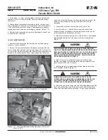
Instructions for
VSR-Series Type 5HK
Vacuum Motor Starter
IB01301027E
Page 21
Page 21
Page 21
Page 21
Page 21
Effective: May 2008
Effective: May 2008
Effective: May 2008
Effective: May 2008
Effective: May 2008
IB01301027E
of plugging or jogging which may require more frequent replace-
ment. Verification of contact wear can be made by following the
procedure below.
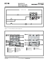
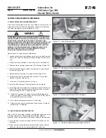
The overtravel gap for a new starter is .080" and is set at the
factory. As the contacts wear the overtravel is reduced. The SL
interrupter design allows for .080" wear before replacement is
required. To verify that the contacts are not worn beyond their
allowable limits, close the contactor with rated control power. Insert
the .020" contactor wear gauge, p/n 5259C11H01, between the
operating plate and the washer on the lower insulator stem of each
pole. Refer to Figure
6-1
. If the gauge cannot be freely inserted on
each pole, all three interrupters must be replaced. Refer to the
section 5.3.1 for instructions on replacing the interrupters.
6.4 INSULATION INTEGRITY CHECK
PRIMARY CIRCUIT:
The integrity of primary insulation may be checked by the AC high
potential test. The test voltage is 15kV, RMS, 60Hz. Conduct the
test as follows:
Close the starter. Connect the high potential lead of the test
machine to one of the phases of the starter. Connect the remaining
two phases and starter frame to ground. Start the machine with
output potential at zero and increase to the test voltage. Maintain
the test voltage for one minute. Repeat for the remaining phases.
Successful withstand indicates satisfactory insulation strength of
the primary circuit.
Open the starter. Connect the high potential lead of the test
machine to one of the poles of the starter. Connect the remaining
poles and starter frame to ground. Start the machine with output
potential at zero and increase to the test voltage. Maintain the test
voltage for one minute. Repeat for the remaining five poles.
Successful withstand indicates satisfactory insulation strength of
the primary circuit.
If a DC high potential machine is used, make certain that the peak
voltage does not exceed the peak of the corresponding AC RMS
test voltage.
SECONDARY CIRCUIT:
Connect all points of the secondary disconnect pins with a shorting
wire. Connect this wire to the high potential lead of the test
machine. Ground the starter frame. Starting with zero, increase
the voltage to 1125 RMS, 60 Hz. Maintain the voltage for one
minute. Successful withstand indicates satisfactory insulation
strength of the secondary control circuit. Remove the shorting
wire.
6.5 CONTACT RESISTANCE CHECK
Testing that measures the contact resistance of the VI’s is not
recommended since the results can vary widely on good contacts.
If a resistance check is performed, the best results will be with a
test module that will force 10 amps through the contacts while
measuring resistance. The resistance should not exceed the
factory test levels by more than 15%.
Do not use a 100 Amp source. Test sets with output
exceeding 10 Amps can damage the fuse elements
NOTICE


