


For more information visit: www.eaton.com
www.eaton.com
www.eaton.com
www.eaton.com
www.eaton.com
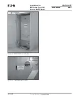
Instructions for
VSR-Series Type 5HK
Vacuum Motor Starter
IB01301027E
IB01301027E
Page 12
Page 12
Page 12
Page 12
Page 12
Effective: May 2008
Effective: May 2008
Effective: May 2008
Effective: May 2008
Effective: May 2008
SECTION 4: INSTALLATION AND INSPECTION
BEFORE PLACING THE STARTER IN SERVICE, CAREFULLY FOLLOW
THE INSTALLATION PROCEDURE BELOW AND THE SAFE PRACTICES
SET FORTH IN SECTION 2. NOT FOLLOWING THE PROCEDURE MAY
RESULT IN INCORRECT STARTER OPERATION LEADING TO DEATH,
BODILY INJURY, AND PROPERTY DAMAGE.
When the starter is first commissioned into service and each time
the starter is returned to service, it should be carefully examined
and checked to make sure it is clean and operating correctly.
4.1 EXAMINATION FOR DAMAGE
Examine the starter for loose or obviously damaged parts. Never
attempt to install nor operate a damaged starter.
4.1.1 NAMEPLATE VERIFICATION
Compare the starter nameplate information with switchgear
drawings for compatibility. Starter and compartment code plates do
match power ratings, but do not match control voltages.
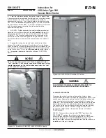
4.2 INITIAL INSPECTION AND OPERATION
Inspect the starter for any damage that occurred during shipment,
storage, and installation.
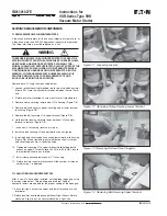
Set the dip switches in the coil control board for the proper control
voltage and dropout time (Figures
4-1
and
4-2
and Tables
4.1
and
4.2
). When control information is supplied, dip switches will be
factory set.
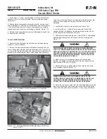
Sequence the control circuit, including closing the starter with the
main power circuits de-energized and locked out.
Verify that the starter will be connected to an incoming power
supply and outgoing load with characteristics agreeing with the
starter rating and coil burden requirements.
WARNING
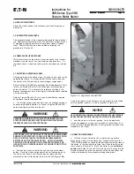
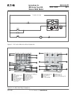
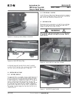
Figure 4-1 Coil Control Board with Dip Switch
Figure 4-2 Coil Control Board Removal
1 2 3 4 5 6
ON
OFF
Dip S
w
itch
Table 4.1 - Dip Switch Setting-Control Voltage
g
n
i
t
t
e
S
1
W
S
2
W
S
3
W
S
z
H
0
5
c
a
V
0
1
1
f
f
O
f
f
O
f
f
O
z
H
0
6
c
a
V
0
2
1
n
O
f
f
O
f
f
O
z
H
0
5
c
a
V
0
2
2
f
f
O
n
O
f
f
O
z
H
0
6
c
a
V
0
4
2
f
f
O
n
O
f
f
O
C
D
V
5
2
1
f
f
O
f
f
O
n
O
g
n
i
t
t
e
S
y
a
l
e
D
4
W
S
5
W
S
6
W
S
s
m
0
3
f
f
O
f
f
O
f
f
O
s
m
0
5
n
O
f
f
O
f
f
O
s
m
0
3
1
f
f
O
n
O
f
f
O
s
m
0
5
2
n
O
n
O
f
f
O
s
m
0
3
3
f
f
O
f
f
O
n
O
Table 4.2 - Control Board Dropout Settings
4.3 VACUUM INTERRUPTER INTEGRITY
Using a dry lint free cloth or a paper towel, clean all the insulating
surfaces of the pole units. Conduct a vacuum interrupting integrity
check as described in Section 6.2.


