


For more information visit: www.eaton.com
www.eaton.com
www.eaton.com
www.eaton.com
www.eaton.com
Instructions for
VSR-Series Type 5HK
Vacuum Motor Starter
IB01301027E
IB01301027E
Page 18
Page 18
Page 18
Page 18
Page 18
Effective: May 2008
Effective: May 2008
Effective: May 2008
Effective: May 2008
Effective: May 2008
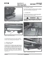
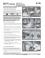
Auxiliary Contacts
An operating lever attached to the rotating shaft operates a set of
auxiliary contacts located on each side of the starter (Figure
5-2
).
The standard configuration is 3NO-3NC contact on each side of the
starter. The auxiliary contacts are rated 600V, 10 amps continuous.
Minimum ratings are 5 volts, 100 milliamps. Refer to Table
5.1
for
make/break ratings.
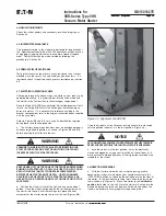
5.2 PHASE BARRIERS
DO NOT PLACE THE STARTER IN ITS COMPARTMENT WITHOUT
THE PHASE BARRIERS IN PLACE. THE ABSENCE OF BARRIERS
CAN CAUSE A CATASTROPHIC FAILURE DURING AN INTERRUP-
TION OR OPERATION, CAUSING DEATH, SEVERE PERSONAL
INJURY OR PROPERTY DAMAGE.
Phase barriers on all 5HK-VSR starters are made of glass polyester
or Lexan. They are all easily removed for easy access to fuses.
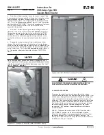
5.3 SECONDARY DISCONNECTS
The VSR control circuit is connected to the switchgear control
through a multi-contact block (See Section 3 for component
location). The movable secondary control contacts mounted on the
breaker are self-aligning, line-contact, slip-type connectors. The
multiple finger arrangement on the breaker makes contact with a
stationary mounted element. The contact surfaces on the station-
ary element are recessed to prevent accidental short-circuiting of
the control circuits.
These secondary disconnects mate in both the operating and test
positions. No special jumper is required.
Mechanical stops prevent over-travel and avoid damage to the
disconnecting devices when the circuit breaker is levered into
operating position.
5.4 INTERLOCKS
There are several interlocks built into the VSR-Series vacuum
starter replacements. Each of these interlocks, though different in
form, duplicate or exceed in function that of the original breaker.
These interlocks exist to safeguard personnel and equipment. The
basic premise behind the interlocking arrangement on the vacuum
replacement starter is that the starter must not be inserted into or
remove from the live circuit while the main contacts are closed.
Also considered in the interlocking is that the starter should pose no
greater risk than necessary to the operator in or out of the cell. In
addition to the original interlocks, VSR-Series starters provide an
anti-close interlock.
INTERLOCKS ARE PROTECTIVE DEVICES FOR PERSONNEL AND
EQUIPMENT. DO NOT BYPASS, MODIFY, OR MAKE INOPERATIVE ANY
INTERLOCKS. DOING SO COULD CAUSE DEATH, SERIOUS PERSON-
NEL INJURY, AND/OR PROPERTY DAMAGE.
5.5 LEVERING-IN INTERLOCK
The levering-in interlock is designed to prevent moving the starter
into or out of the Connect position, if the starter contacts are
closed. 5HK-VSR interlocks are completely compatible with the
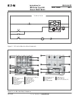
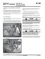
Figure 5-3 SL Contactors Assembly
Operating Plate
Overtravel
4
5
Armature Shaft
Moving Armature
Stop
Contactor Closed
Contactor Open
1
2
3
Operating Plate
Return Spring
4
5
Armature Shaft
Moving Armature
Stop
1
2
3
4
5
1
2
3
4
5
1
2
3
WARNING
WARNING


