69
Chapter 5 - Fan control application
POWERXL DM1 SERIES VARIABLE FREQUENCY DRIVES
MN040049EN
—September 2021 www.eaton.com
Table 28. Protections (Cont.).
P6.1 - Motor.
P6.1.4
ab
Motor thermal protection
ID 310
Minimum value:
N.A.
Maximum value:
N.A.
Default value:
2
Options:
0 = No response.
1 = Warning.
2 = Fault, stop mode after fault according to parameter stop mode.
3 = Fault, stop mode after fault always by coasting.
Description:
If a fault condition is selected, the drive will stop and activate the fault stage based off the % of calculated motor temperature. The
calculated motor temp is based off the install power on values of the drive and monitoring values as the drive is running. Deactivating
this protection, i.e., setting parameter to 0, will reset the thermal stage of the motor to 0%.
P6.1.5
b
Motor thermal FO current
ID 311
Minimum value:
0.00%
Maximum value:
150.00%
Default value:
100.00%
Description:
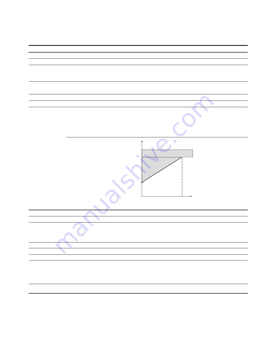
The current can be set between 0 - 150.0% x InMotor. This parameter sets the value for thermal current at zero frequency.
The default value is set assuming that there is no external fan cooling the motor. If an external fan is used, this parameter can be set to
90% (or even higher).
Note:
The value is set as a percentage of the motor nameplate data, P1.6 (nominal current of the motor), not the drive’s nominal output
current. The motor’s nominal current is the current that the motor can withstand in direct on-line use without being overheated.
If you change the parameter nominal current of motor, this parameter is automatically restored to the default value.
Setting this parameter does not affect the maximum output current of the drive.
100%
0
Overload Area
Motor Thermal
FO Current
= 40%
Cooling
P
f
fn
IT
P6.2.2
ab
Input phase fault
ID 332
Minimum value:
N.A.
Maximum value:
N.A.
Default value:
2
Options:
0 = No response;
1 = Warning;
2 = Fault, stop mode after fault according to parameter stop mode;
3 = Fault, stop mode after fault always by coasting; or
4 = Single phase power limit.
Description:
The input phase supervision ensures that the input phases of the frequency converter have approximately equal current draw.
P6.2.3
ab
4 mA input fault
ID 306
Minimum value:
N.A.
Maximum value:
N.A.
Default value:
0
Options:
0 = No response.
1 = Warning.
2 = Warning, the frequency from 10 seconds back is set as reference.
3 = Warning, the preset frequency P6.2.4 is set as reference.
4 = Fault, stop mode after fault according to parameter stop mode.
5 = Fault, stop mode after fault always by coasting.
Description:
A warning or a fault action and message is generated if the 4 - 20 mA reference signal is used and the signal falls below 4 mA for 5
seconds, or below 0.5 mA for 0.5 seconds. The information can also be programmed into relay outputs RO1 and RO2.
.


