INSTALLATION
Eaton 9140 UPS (7.5–10 kVA) User's Guide
S
164201622 Rev 3
www.eaton.com/powerquality
56
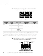
Table 3. UPS Output Wiring Specifications
UPS Terminal
Block
Terminal
Position
UPS Wire Function
Terminal Wire
Size Rating
1
Tightening
Torque
Output
1
Line / Line 1 Out
13.3 mm
2
(6 AWG)
1.8 Nm (16 lb in)
2
Neutral Out
2
3
Output Ground
1
Use 13.3 mm
2
(6 AWG) 90
_
C copper wire minimum. For ease of installation, use appropriately sized ferrules on the end
of each wire.
2
Line 2 Out (single-phase 208V only).
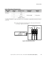
12.
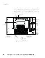
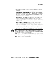
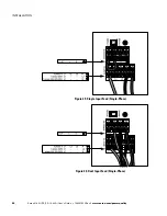
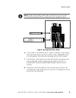
Set the phase input selector switch for single-phase or three-phase
input. See Figure 31 on page 53 for the location of the switch.
NOTE
The UPS will not operate if the input is wired for single-phase and the selector
switch is set for three-phase.
NOTE
If the input is wired for three-phase and the selector switch is set for single-phase,
the UPS will operate on single-phase. Operating the UPS in this configuration is NOT
recommended and could result in unintended upstream breaker tripping and overheating of
the input wiring, if the breaker and wiring are sized for three-phase input.
NOTE
Resetting the phase input selector switch while the UPS is running has no effect on
UPS operation. The UPS reads the position of the switch only when powering on.
13.
Replace the input and output terminal block covers.
14.
If your rack has conductors for grounding or bonding of ungrounded
metal parts, connect the ground cable (not included) to the ground
bonding screw. See Figure 28 on page 50 for the location of the
ground bonding screw.
NOTE
DO NOT protect laser printers with the UPS because of the exceptionally high power
requirements of the heating elements.
NOTE
Verify that the total equipment ratings do not exceed the UPS capacity to prevent an
overload alarm.
15.
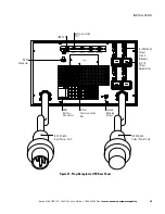
Plug the equipment to be protected into the UPS output
receptacles, but do not turn on the protected equipment (see
Figure 28 on page 50).
16.
Make any necessary provisions for cord retention and strain relief.

