


COMMUNICATION
Eaton 9140 UPS (7.5–10 kVA) User's Guide
S
164201622 Rev 3
www.eaton.com/powerquality
78
DB-9 Communication Ports
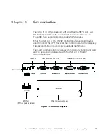
The Eaton 9140 provides two DB-9 ports on the UPS rear panel. The
service port is not intended for customer use and does not support
standard communication protocols. The RS-232 port is available for UPS
monitoring, control, and flash upgrades.
To establish communication between the UPS and a computer, connect
your computer to the RS-232 UPS communication port using the
supplied serial communication cable (see Figure 38 on page 75).
When the communication cable is installed, power management
software can exchange data with the UPS. The software polls the UPS
for detailed information on the status of the power environment. If a
power emergency occurs, the software initiates the saving of all data
and an orderly shutdown of the equipment.
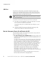
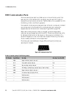
The cable pins are identified in Figure 39 and the pin functions are
described in Table 6.
3
8
7
9
1
6
2
4
5
Figure 39. Communication Port
Table 6. Communication Port Pin Assignment
Pin Number
Signal Name
Function
Direction from the UPS
1
GND
Signal common (tied to chassis)
—
2
TxD
Transmit to external device
Out
3
RxD
Receive from external device
In
4
DTR
PnP (Plug and Play) from external device (tied to Pin 6)
In
5
GND
Signal common (tied to chassis)
—
6
DSR
To external device (tied to Pin 4)
Out
7
—
No Connection
—
8
—
No Connection
—
9
—
No Connection
—


