


INSTALLATION
Eaton 9140 UPS (7.5–10 kVA) User's Guide
S
164201622 Rev 3
www.eaton.com/powerquality
58
REPO and ROO Installation
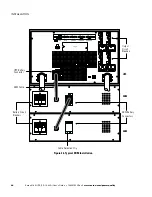
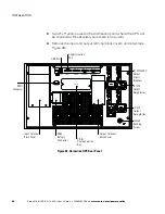
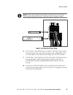
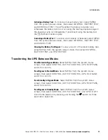
The Eaton 9140 includes a two-position terminal (see Figure 35) that can
be either left open or configured one of two ways:
S
As a remote emergency power-off (REPO) contact
that allows power to be
switched off at the UPS output from a customer-supplied switch in a
remote location.
S
As a remote on/off (ROO) contact
that allows the UPS to be turned on
and off from a customer-supplied switch in a remote location.
Figure 35. REPO/ROO Connection
W
A
R
N
I
N
G
The REPO/ROO circuit is an IEC 60950 safety extra low voltage (SELV) circuit. This circuit
must be separated from any hazardous voltage circuits by reinforced insulation.
C
A
U
T
I
O
N
To ensure the UPS stops supplying power to the load during any mode of operation, the
input power must be disconnected from the UPS when the emergency power-off function is
activated.
NOTE
For Europe, the emergency switch requirements are detailed in Harmonized
document HD-384-48 S1, “Electrical Installation of the Buildings, Part 4: Protection for Safety,
Chapter 46: Isolation and Switching.”
For more information about how the REPO and ROO features function,
see “Remote Emergency Power-off and Remote On/Off” on page 76.


