

INSTALLATION
Eaton 9140 UPS (7.5–10 kVA) User's Guide
S
164201622 Rev 3
www.eaton.com/powerquality
28
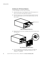
14.
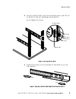
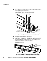
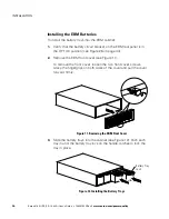
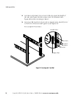
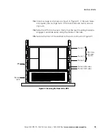
Secure the front of the cabinet to the rack as shown in Figure 8.
Position 2 (M5 screw)
Position 8 (M6 screw
and clip/cage nut)
Position 3 (M5 screw)
Figure 8. Securing the Front of the EBM
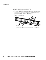
NOTE
To install the optional seismic mounting brackets, the length of the rails must be
between 28.5 and 32 inches.
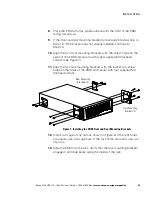
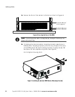
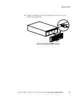
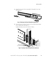
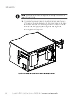
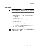
15.
If installing the optional seismic mounting brackets, align the two
EBM seismic mounting brackets with the screw holes on the sides
of the EBM above the rear mounting brackets. Loosely secure the
brackets with four supplied wing bolts. See Figure 9.
Do not tighten the wing bolts.
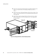
Figure 9. Installing the Optional EBM Seismic Mounting Brackets