

PR2000LCD / PR2200LCD / PR3000LCD
User’s Manual
K01-0000252-00
(SAVE THESE INSTRUCTIONS)
This manual contains important safety instructions. Please read and follow all instructions carefully during installation and operation of the unit.
Read this manual thoroughly before attempting to unpack, install, or operate your UPS.
CAUTION!
To prevent the risk of fire or electric shock, install in a temperature and humidity controlled indoor area free of conductive
contaminants. (Please see specifications for acceptable temperature and humidity range).
CAUTION!
To reduce the risk of electric shock, do not remove the cover except to service the battery. Turn off and unplug the unit before
servicing the batteries. There are no user serviceable parts inside except for the battery.
CAUTION!
Hazardous live parts inside can be energized by the battery even when the AC input power is disconnected.
CAUTION!
The
UPS must be connected to an AC power outlet with fuse or circuit breaker protection. Do not plug into an outlet that is not
grounded. If you need to de-energize this equipment, turn off and unplug the unit.
CAUTION!
To avoid electric shock, turn off the unit and unplug it from the AC power source before servicing the battery or installing a computer
component.
CAUTION!
To reduce the risk of fire, connect only to a circuit provided with 20 amperes maximum branch circuit over current protection in
accordance with the National Electric Code, ANSI/NFPA 70.
DO NOT USE FOR MEDICAL OR LIFE SUPPORT EQUIPMENT!
CyberPower Systems does not sell products for life support or medical
applications.
DO NOT
use in any circumstance that would affect the operation and safety of life support equipment, medical applications, or
patient care.
DO NOT USE WITH OR NEAR AQUARIUMS!
To reduce the risk of fire or electric shock, do not use with or near an aquarium.
Condensation
from the aquarium can cause the unit to short out.
DO NOT LIFT USING FACEPLATE.
Two people are required to lift this unit. Lift this unit from sides only.
INTRODUCTION
Thank you for selecting a CyberPower Systems UPS product. This UPS is designed to provide unsurpassed power protection, operation and
performance during the lifetime of the product.
UNPACKING
Inspect the UPS upon receipt. The box should contain the following:
(a) UPS unit (b) User’s manual (c) Emergency Power Off cable (gray) (d) PowerPanel
®
Business Edition software CD (e) Serial cable (f) USB
A+B type cable (g) Warranty registration card (h) Function Setup Guide
OVERVIEW
The PR2000LCD/PR2200LCD/PR3000LCD UPS provides complete power protection from utility power that isn't always consistent. The
PR2000LCD/PR2200LCD/PR3000LCD features surge protection against power surges and maintenance free batteries for long lasting battery
backup during power outages. In addition to ensuring consistent power to your computer system and the
PR2000LCD/PR2200LCD/PR3000LCD also includes software that will automatically save your open files
and shutdown your computer system during a utility power loss.
AUTOMATIC VOLTAGE REGULATOR
The
PR2000LCD/PR2200LCD/PR3000LCD
stabilizes inconsistent utility power voltage to nominal levels that
are safe for equipment. Inconsistent utility power may be damaging to important data files and hardware,
but with Automatic Voltage Regulation (AVR),
damaging voltage levels are corrected to safe levels. AVR
automatically increases low utility power and decreases high utility power to a consistent and safe
110/120 volts.
HOW TO DETERMINE THE POWER REQUIREMENTS OF YOUR EQUIPMENT
1.
Ensure that the equipment plugged into the outlets does not exceed the UPS unit’s rated capacity (1920VA/1920W for PR2000LCD,
2200VA/1980W for PR2200LCD, 3000VA/2700W for PR3000LCD). If the rated capacities of the unit are exceeded, an overload condition
may occur and cause the UPS unit to shut down or the circuit breaker to trip.
HARDWARE INSTALLATION GUIDE
1. Your new UPS may be used immediately upon receipt. However, to ensure the battery’s maximum
charge capacity, it is recommended that you charge the battery for at least 8 hours. Your UPS is equipped
with an auto-charge feature. When the UPS is plugged into an AC outlet, the battery will automatically
charge whether the UPS is turned on or off.
2. Note: This UPS is designed with a safety feature to keep the system from being turned on during shipment.
The first time you turn the UPS on, you will need to have it connected to AC power or it will not power up.
3. With the UPS unit turned off and unplugged, connect your computer, monitor, and any other
peripherals requiring battery backup into the
battery power supplied outlets.
DO NOT plug a laser printer, paper shredder, copier, space heater, vacuum, sump pump or other large
electrical devices into the “Battery and Surge Protected Outlets”. The power demands of these devices may overload and damage
the unit.
4. Plug the UPS into a 2 pole, 3 wire grounded receptacle (wall outlet). Make sure the wall branch outlet is protected by a fuse or circuit
breaker and does not service equipment with large electrical demands (e.g. air conditioner, copier, etc…). The warranty prohibits the use of
extension cords, outlet strips, and surge strips.
5. Press the power switch to turn the unit on. The Power On indicator light will illuminate and the unit will “beep”.
If an overload is detected, an audible alarm will sound and the unit will emit one long beep. To correct this, turn the UPS off and unplug at
least one piece of equipment from the battery power supplied outlets. Make sure the circuit breaker is depressed and then turn the UPS on.
6. To maintain optimal battery charge, leave the UPS plugged into an AC outlet at all times.
7. To store the UPS for an extended period, cover it and store with the battery fully charged. While in storage, recharge the battery every three
months to ensure battery life.
8. Insure the wall outlet and UPS are located near the equipment being attached for proper accessibility.
9. The LCD module is wall-mountable for extended distance control. Follow the steps below for installation procedure.
a. Remove the LCD module from the front panel.
b. Hang the LCD module on the wall.
c. Replacing the LCD on the UPS - To place the LCD back on the UPS, roll up the LCD cable, return it to the space between the front panel &
battery cover, and replace the LCD.
DESCRIPTION
Front Panel
1
Power Switch / Power On Indicator
Used as the master on/off switch for equipment connected to the battery power supplied outlets.
2
Online Indicator
This LED is illuminated when the utility power is normal and the UPS outlets are providing power, free of surges and spikes.
3
On Battery Indicator
During a severe brownout or blackout, this LED is illuminated and an alarm sounds (two short beeps followed by a pause) to indicate the
UPS is operating from its internal batteries.
4
Fault
This LED is illuminated if there is a problem with the UPS.
5
Replace Battery Indicator
This LED is illuminated to remind users to replace the battery.
6
Status/Tab Button
For UPS status information, press the button for 1 second. For additional information including
the use of the button as a Tab, please refer to the
Function Setup Guide
.
7
Setup/Enter Button
Press the Setup button for 1 second to enter setup menu and then select the functions for
configuration. For more information about the Setup/Enter button, please refer to the
Function
Setup Guide
.
8
Control/Up Button
Press the Control button for 1 second to enter control menu and then select the functions for
configuration. This button is also used to scroll up. For more information about the Control/Up
button, please refer to the
Function Setup Guide
.
9
Test/Down Button
Press the Test switch for 1 second to enter test menu and then select the functions for
configuration. This button is also used to scroll down. For more information about the Test/Down
button, please refer to the
Function Setup Guide
.
10 Logs/Esc Button
Press the Logs button for 1 second to view the events or logs that have been recorded.
This button is also used to exit a menu. For more information about Logs/Esc button,
please refer to the
Function Setup Guide
.
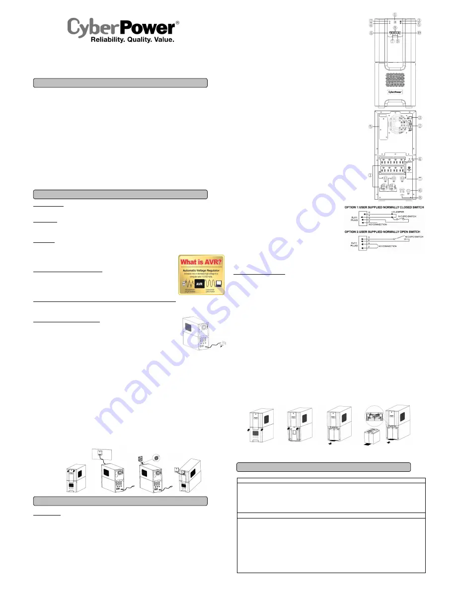
Rear Panel
1
Battery and Surge Protected Outlets
The unit has ten battery powered and surge protected outlets for connected equipment to
ensure temporary uninterrupted operation of your equipment during a power failure.
(DO NOT plug a laser printer, paper shredder, copier, space heater, vacuum, sump
pump or other large electrical devices into the “Battery and Surge Protected Outlets”.
The power demands of these devices may overload and damage the unit.)
2
Serial/USB Ports to PC
The Serial and USB ports allow connection and communication between the
computer and the UPS unit. Note: Only one port can be used at a time.
3
EPO Port
Use the provided gray EPO cable to connect to a provided EPO contact switch.
Follow the appropriate circuit diagram to the right to wire the cable to your
EPO configuration. The EPO remote switch is a switch installed in an outside
area, connected to the unit via the Emergency Power Off cable. In case of an
emergency, it can be used to immediately cut-off power from the UPS.
4
TVSS Ground
The TVSS GND only used for dielectric voltage-withstand test on production.
5
SNMP/HTTP Network Slot
Remove the cover panel to install an optional RMCARD to remotely monitor
and manage your UPS over a network.
6
Input Circuit Breaker
Located on the back of the UPS, the circuit breaker provides overload and
fault protection.
7
Output Circuit Breaker
Located on the back of the UPS, the circuit breaker provides overload and fault protection.
8
AC Input Power Cord
Heavy-duty power cord.
REPLACING THE BATTERY
Replacement of batteries located in an
OPERATOR ACCESS AREA
.
1.
When replacing batteries, replace with the same number of the following battery: CyberPower / RB12170X4 for the PR2000LCD,
PR2200LCD and PR3000LCD. Contact CyberPower Systems about replacement batteries.
2.
CAUTION!
Risk of Energy Hazard, 12V, maximum 20 Ampere-hour battery. Before replacing batteries, remove conductive jewelry such
as chains, wrist watches, and rings. High energy conducted through these materials could cause severe burns.
3.
CAUTION!
Do not dispose of batteries in a fire. The batteries may explode.
4.
CAUTION!
Do not open or mutilate batteries. Released material is harmful to the skin and eyes. It may be toxic.
CAUTION - RISK OF EXPLOSION IF BATTERY IS REPLACED BY AN INCORRECT TYPE. DISPOSE OF USED BATTERIES ACCORDING
TO LOCAL REGULATIONS.
BATTERY REPLACEMENT PROCEDURE:
1.
Turn off and unplug all connected equipment.
2.
Turn the UPS off and unplug it from the AC power source.
3.
Remove the front panel of the UPS.
4.
Remove two screws from the battery compartment cover and slide the cover completely off of the unit.
5.
Pull out the battery pack on the outside from the compartment. Disconnect the battery connector from the batteries.
6.
Before removing the battery pack on the inside, unlock the cable tie and pull out the battery wires. Disconnect the battery connector from
the batteries. Pull out the battery pack on the inside from the compartment.
7.
Install the replacement battery pack on the inside by connecting the wire bundle connector (composed of one red wire and one black wire)
to the connector from the battery pack. Lock the battery wires back with the cable tie.
8.
Install the replacement batteries on the outside by connecting the wire bundle connector (composed of one red wire and one black wire) to
the connector from the battery pack. Put the battery pack on the outside back into the compartment.
9.
Re-install the battery compartment cover and tighten the retaining screws.
10.
Put the front panel back on the UPS.
11.
Connect to AC power and charge the new batteries for up to 16 hours to insure a full charge.
Note: The battery pack on the outside has a fuse, while the battery pack on the inside has not.
REMINDER:
Batteries are considered
HAZARDOUS WASTE
and must be disposed of properly. Most retailers that sell lead-acid batteries
collect used batteries for recycling, as required by local regulations.
Status Menu/Switch
Operation Mode
Load Power
Load VA
Load Amps
Load Energy
Estimated Runtime
Battery Information
Input
Output
Last Self Test
Date & Time
NCL Output
Setup Menu/Switch
Setup Wizard
Utility Power
MIN O/P Voltage
MAX O/P Voltage
LCD Auto Sleep
Cycling Display
Audible Alarm
Temporarily Mute
Sensitivity
Charge Mode
Low Battery Warning
Date & Time
Battery Change Date
Firmware Update
Power Meter Reset
Back to Default
Delay Turn On
Delay Turn Off
Reboot Duration
Minimum Restore Capacity
Uptime on Battery
Reserve Runtime
BASIC OPERATION
INSTALLING YOUR UPS SYSTEM
IMPORTANT SAFETY WARNINGS
DEFINITIONS FOR ILLUMINATED LCD INDICATORS


