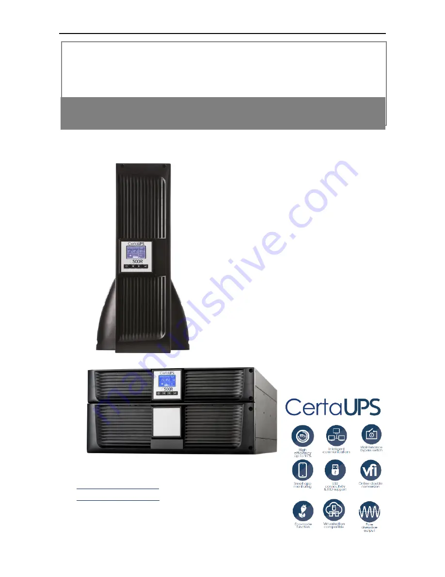
manualshive.com logo in svg
background image


C500R 6-10kVA (B) 

Rack/Tower 6-10kVA 


Installation/Manual 

Service and support 

WWW.CERTAUPS.COM 
[email protected] 

T: +44 (0)1246 431 431 

Содержание PowerControl C500R-060-B UPS

Страница 1: ...C500R 6 10kVA B Rack Tower 6 10kVA Installation Manual Service and support WWW CERTAUPS COM INFO CERTAUPS COM T 44 0 1246 431 431 ...

Страница 2: ...EL 13 3 5 RACK MOUNT SETUP 14 3 6 TOWER SETUP 19 3 7 INSTALLATION OF UPS WITH AC INPUTS 19 4 POWER CABLES CONNECTION STARTUP 22 4 1 ACCESS TO TERMINAL BLOCK 22 4 2 COMMON INPUT SOURCES CONNECTION 23 4 3 SEPARATE INPUT SOURCES CONNECTION 23 4 4 FREQUENCY CONVERTER CONNECTION 24 4 5 UPS INITIAL STARTUP 26 4 6 PARALLEL OPERATION 27 5 OPERATION 32 5 1 DISPLAY PANEL 32 5 2 OPERATING MODE 35 5 3 TURNING...

Страница 3: ...ATTERY OR UPS 56 7 SPECIFICATIONS 57 7 1 ELECTRICAL SPECIFICATION 57 7 2 DIMENSION AND WEIGHT 58 7 3 OPERATING ENVIRONMENT 58 8 TROUBLESHOOTING 59 8 1 TYPICAL ALARMS AND CONDITIONS 59 9 COMMUNICATION 63 9 1 USB INTERFACE 63 9 2 RS 232 INTERFACE 64 9 3 DRY CONTACT INTERFACE 64 9 4 INTELLIGENT SLOT 66 10 SOFTWARE 67 ...

Страница 4: ...nout and line noise Power outages can occur when you least expect them and power quality can be erratic These power problems have the potential to corrupt critical data destroy unsaved work sessions and damage hardware causing hours of lost productivity and expensive repairs With the C500R UPS you can safely eliminate the effects of power disturbances and ensure the protection of your equipment Th...

Страница 5: ...gure 1 2 Online C500R 100 B UPS Online R T UPS as Tower installation Figure 1 3 Online C500R 060 B UPS Figure 1 4 Online C500R 100 B UPS Providing outstanding performance and reliability the C500R benefits ...

Страница 6: ... powering up the UPS even if utility power is not available Standard communication options one RS 232 communication port one USB communication port Optional connectivity cards with enhanced communication capabilities Extended runtime with up to four Extended Battery Modules EBMs per UPS Optional installation method Rack Tower Remote shutdown control through the Remote Emergency Power off REPO port...

Страница 7: ... in such a way that no one can step on or trip over them An integral single emergency switching device which prevents further supply to the load by the UPS in any operation mode should be provided in the building wiring installation An appropriate disconnect device as short circuit backup protection should be provided in the building wiring installation This is permanently connected equipment it s...

Страница 8: ...llation wiring To reduce the risk of fire connect only to a circuit provided with branch circuit overcurrent protection with an ampere rating in accordance with the IEC EN 60934 standard or your local electrical code and have a contact air gap of at least 3 mm Uninterruptible power supply output power 240V C500R 060 B 40 amp 2 pole circuit breaker C500R 100 B 63 amp 2 pole circuit breaker You can ...

Страница 9: ...sk of electric shock Even after the unit is disconnected from the mains power supply building wiring terminal components inside the UPS are still connected to the battery which have potentially dangerous voltages Before carrying out any kind of service and or maintenance please disconnect the batteries Verify that no current is present and no hazardous voltage exists in the capacitor or BUS capaci...

Страница 10: ...losion 5 Do not open or destroy batteries Effluent electrolyte can cause injury to the skin and eyes It may be toxic Please replace the fuse only with the same type and of the same amperage in order to avoid fire hazards The UPS should only be dismantled or worked on by qualified maintenance personnel 2 4 Transport Please transport the UPS only in the original packaging to protect against shock an...

Страница 11: ...1000 4 2 Level 4 RS IEC EN61000 4 3 Level 3 EFT IEC EN 61000 4 4 Level 4 SURGE IEC EN 61000 4 5 Level 4 CS IEC EN 61000 4 6 Level 3 Power frequency Magnetic field IEC EN 61000 4 8 Level 3 Low Frequency Signals IEC EN 61000 2 2 Warning This is a product for commercial applications If used in an industrial environment extra precautions may be required ...

Страница 12: ...for concealed damage Note Check the battery recharge date on the shipping carton label If the date has passed and the batteries were never recharged do not use the UPS Contact your service representative 3 2 Unpacking the Carton CAUTION If the carton unpacked in a low temperature environment it may cause condensation in or on the cabinet of UPS Do not install the UPS until the inside and outside o...

Страница 13: ...10 Step 1 Open the outer carton and remove the accessories package in the cabinet see Figure 3 1 3 2 C500R 060 B UPS Figure 3 1 Unpacking the Carton of C500R 060 B UPS C500R 100 B UPS ...

Страница 14: ...er carton using the handles on the cardboard and set it on a flat stable surface see Figure 3 3 3 4 Place the cabinet in a protected area that has adequate airflow and is free of humidity flammable gas and corrosion Lifting the Cabinet CAUTION The cabinet is heavy Lifting the cabinets out of the carton requires two persons at least ...

Страница 15: ...60 B carton Figure 3 4 Lifting the Cabinet out of C500R 100 B carton Step 3 Discard or recycle the packaging in a responsible manner or store it for future use 3 3 UPS Rear Panel This section shows the rear panel of the C500R models C500R 060 B model ...

Страница 16: ... 6 Online C500R 100 B Rear Panel 3 4 UPS Front Panel This section shows the front panel of the Online R T UPS The Online series have the same LCD panel and the same control button LCD panel On Off Button Scroll Button Up or Back Select Button Scroll Button Down of Forward ...

Страница 17: ...ON removal or replacement of the batteries should be performed or supervised by authorised personnel with knowledge of batteries CAUTION If installing an EBM install the EBM directly below the UPS 3 5 1 Install the UPS and EBM Extended Battery Modules in a rack 1 Open the front panel and set aside Figure 3 8 Open the front panel left C500R 060 B Model right C500R 100 B Model 2 Remove the battery p...

Страница 18: ...Packs 4 Install the UPS and terminal box s ears to the UPS Figure 3 11 Install the UPS and terminal box s ears to the UPS 5 Select the proper holes in the rail for positioning the cabinet in the desired location in the rack Locate the rails at the bottom of the 3U space allocated for the each UPS and EBM 6 Install the sliding rails in the rack then install the UPS in the sliding rail ...

Страница 19: ... then replace the front panel Figure 3 13 Install the UPS to the rail then replace the front panel 8 For 6K Replace the battery tray and connect the internal battery connector then replace the protection plate and the front panel 9 If installing additional UPS repeat from Step 1 to Step 8 for each cabinet ...

Страница 20: ...talling the EBMs To install EBMs C500R 060 B Model 1 Plug the EBM cable into the UPS battery connector Figure 3 14 Plug the EBM cable into the UPS battery connector 2 Replace UPS s front panel and EBM s front panel ...

Страница 21: ...ace UPS s front panel and EBM s front panel C500R 100 B Model Figure 3 16 Plug the EBM cable into the UPS battery connector CAUTION Please connect the EBM to protective ground with 10mm2 wire for B500 R100 B model firstly ...

Страница 22: ...tallation of UPS with AC inputs CAUTION Online C500R 060 B C500R 100 B series support that the UPS can have separate AC inputs So before connecting wires of seperate AC inputs you should confirm that their earthing systems are identical Otherwise a transformer is necessary ...

Страница 23: ...n Normal and Bypass AC inputs UPS with separate Normal and Bypass AC inputs Earthing systems are identical Earthing systems are separate Three different installations can be choosen 1 Transformer in the Normal AC input ...

Страница 24: ...21 2 Transformer in the Bypass AC input 3 Both of them have transformer Frequency converter without Bypass AC input ...

Страница 25: ...nal block Common input sources connection Separate input sources connection Frequency converter connection UPS initial startup 4 1 Access to terminal block Access to terminal block remove the 2 screws of the terminal block cover Figure 4 1 Terminal box of C500R 060 B C500R 100 B ...

Страница 26: ...ion must be carried out by qualified electrical personnel CAUTION Always connect the earth wire first Figure 4 2 Common input sources connection 4 3 Separate input sources connection CAUTION This type of connection must be carried out by qualified electrical personnel ...

Страница 27: ...he earth wire first Figure 4 3 Separate input sources connection 4 4 Frequency converter connection CAUTION This type of connection must be carried out by qualified electrical personnel CAUTION Always connect the earth wire first ...

Страница 28: ... section 4mm2 10AWG 6mm2 8AWG Input L N G Min conductor cross section 4mm2 10AWG 6mm2 8AWG Input fuse 60A 80A Output L N Min conductor cross section 4mm2 10AWG 6mm2 8AWG External Battery Cabinet Positive Pole Negative pole Neutral Pole Min conductor cross section 4mm2 10AWG 2 5mm2 2 12AWG 2 External Battery Cabinet Fuse 60A 80A in Positive Pole Negative pole Neutral Pole ...

Страница 29: ...PS Initial Startup To start up the UPS Verify that the total equipment ratings do not exceed the UPS capacity to prevent an overload alarm 1 Verify that the internal batterties are connected 2 If optional EBMs are installed verify that the EBMs are connected to the UPS 3 Set the upstream circuit breaker not included to the I position ON The LCD will display the logo for several seconds and then go...

Страница 30: ...dundancy The parallel structure is 1 1 As long as the UPS is equipped with parallel cables up to 2 UPSs can be connected in parallel to configure a sharing and redundant output power 4 6 2 Installation and operation How to install a new parallel UPS system 1 Before installing a new parallel UPS system prepare the input and output wires the input and output breakers and the parallel cable 2 An appr...

Страница 31: ...28 Figure 4 5 and ensure all breakers are open ...

Страница 32: ...29 Figure 4 5 a Parallel systerm wiring diagram of 6K 10K Figure 4 5 b Parallel System Installation Diagram 6 Turn on the mains Breakers and the input breakers for the two parallel UPS ...

Страница 33: ...for the parallel system 2 Regulate the output voltage of the new UPS check if the output voltage difference between the new UPS and the parallel system is less than 0 5V 3 Ensure the bypass of the parallel system is normal and the bypass setting is enable then press the button to turn off the UPS the UPS will now work in bypass mode 4 Set the main maintenance switch or static switch from UPS to BP...

Страница 34: ...ch from UPS to BPS then switch off the output breakers the input breakers and mains breaker for the two UPS and the UPS will shut down 4 Switch off the main O P breaker and O P breaker for the UPS system 5 Remove the UPS and cables and wires 6 Switch on the mains breaker and input breaker of the reserved UPS ensure the UPS works in bypass mode 7 Switch on the O P breaker and main O P breaker 8 Tra...

Страница 35: ...lour backlight Standard back light is used to light up the display with white text and a blue background When the UPS has a critical alarm the backlight changes the text to dark amber and the background to red See Figure below Figure 5 1 C500R 060 B C500R 100 B On line UPS Control Panel ...

Страница 36: ...ress this button for 1s to exit the present menu to default system status display menu without executing a command or changing a setting Scroll up Press this button for 100ms 1s to scroll up the menu option Scroll down Press this button for 100ms 1s to scroll down the menu option Enter next menu tree Press this button for 100ms 1s to select the present menu option or enter next menu but do not cha...

Страница 37: ...g on the LCD will display the logo for several seconds and then go to the default page which shows the UPS status summary The display automatically returns to the default UPS status summary screen when no button has been pressed within 15 minutes The UPS status summary screen provides the following information Status summary including mode and load Alarm status if any are present Notes alarm inclu...

Страница 38: ...for LCD are illustrated in chapter 5 4 5 2 Operating mode Different graphic symbols could be displayed according to current operating mode or status 5 2 1 Line mode An example of the LCD display in Line mode is shown in the following diagram Figure 5 3 Line mode ...

Страница 39: ...tery mode the buzzer beeps once every 4 seconds 5 2 3 Bypass with output The LCD display in bypass mode with output is shown in the following diagram The UPS does not have the backup function when it is in bypass mode The power used by the load is supplied from the utility power via the internal filter The UPS will beep once every 2 minutes in bypass mode ...

Страница 40: ...ode without output 5 2 5 HE mode High Efficiency mode When the UPS is turned on the power is supplied from the utility power via the internal filter while the utility power is in normal range so the high efficiency can be gained in the HE mode Once the mains is lost or abnormal the UPS will transfer to Line mode or Battery mode and the load is supplied continuously ...

Страница 41: ...38 Figure 5 7 HE mode ...

Страница 42: ... frequency 50Hz or 60Hz Once the mains is lost or abnormal the UPS will transfer to battery mode and the load is supplied continuously Figure 5 8 Converter mode 1 The function could be enabled through the LCD setting or the software Winpower etc 2 The load should be derating to 80 in converter mode 5 2 7 Warning When a warning occurs it indicates some abnormal problems during the operation of the ...

Страница 43: ...40 Figure 5 9 Warning 5 2 8 Fault When a fault occurs the UPS will directly cut off the output or transfer to bypass and keep alarming The backlight of LCD will also turn to red Figure 5 10 Fault ...

Страница 44: ...y one to decrease the loads connected to the UPS Figure 5 11 Overload While doing the battery test LEDs will be illuminated and the battery test will be shown on the display Figure 5 12 Battery test If the battery status detected is bad battery detected or battery disconnected the battery failure symbol will be shown and the UPS will ...

Страница 45: ...all connected loads before turning off the UPS 5 3 1 Turning on UPS with utility 1 Check all the connections are correct 2 Power on the UPS The fan begins to rotate and the LCD will show the logo Then LCD will show the default UPS status summary screen 3 Pressing button continuously for more than 1 second The buzzer will beep for 1 second and the UPS will start to turn on 4 A few seconds later the...

Страница 46: ...ion of the UPS output 5 3 3 Turning off the UPS with utility 1 To turn off the inverter of UPS press button continuously for more than 3 seconds and the buzzer will beep for 3 seconds The UPS will go into Bypass mode at once 2 When completing the above action UPS output voltage is still present In order to cut off the UPS output simply cut off the utility power supply A few seconds later the LCD d...

Страница 47: ...ptimize the function of UPS 5 4 1 The main menu In the default UPS status summary screen when pressing or 1 second the detailed information about the alarm the parallel system and the battery will be shown In the default UPS status summary screen when pressing 1s the display will enter the main menu tree The main menu tree includes six branches the UPS status menu event log menu measurement menu c...

Страница 48: ...45 Figure 5 14 Main menu tree ...

Страница 49: ...of UPS status the display will enter the next UPS status menu tree The content of UPS status menu tree is the same as the default UPS status summary menu By pressing 1 second the display will return the last main menu tree Figure 5 15 UPS status menu tree ...

Страница 50: ...corded here This information includes the illustration the event code and the precise time when the event happened By pressing or 1 second all the events can be displayed one by one The max number of records is 50 When the number is larger than 50 the latest will replace the previous records By pressing 1 second the display will return to the last main menu tree ...

Страница 51: ... the display will enter the next measurement menu tree A lot of detailed useful information can be checked here for example the output voltage and frequency the output current the load capacity the input voltage and frequency etc By pressing 1 second the display will return the last main menu tree ...

Страница 52: ...menu to clear EPO status then the UPS will stop the alarm and recover to Bypass mode The UPS should be turned on by manual operation 3 Reset Fault status when a fault occurs the UPS remains in Fault mode and alarms To recover to normal status enter this menu to reset error status then the UPS will stop the alarm and recover to Bypass mode The cause of the fault should be checked and dealt with bef...

Страница 53: ...Single UPS Battery Test Status Battery test OK Schedule battery test no Single UPS Parallel UPS Parallel UPS Battery test Status Battery test OK Schedule battery test no Clear EPO Status Status EPO active Clear no Reset fault state Status Fault active Reset fault no Clear event log Total events 50 Clear event log no Restore factory setting Reset no 1s 1s ...

Страница 54: ...S serial number firmware serial number model type will be shown here By pressing 1 second the display will return the last main menu tree Figure 5 19 Identification menu tree 5 4 7 The setting menu Please contact your local distributor for further information before using the settings An inappropriate option setting by user may result in potential failure or protecting function loss even directly ...

Страница 55: ...nabled disabled Bypass voltage low limit limit Bypass voltage high 215V 264V 245 276V 120 215V Bypass frequency Low limit 10 45 0Hz 1 User password disabled Password 0000 Auto Restart enabled enabled disabled Automatic battery Tests period 7days 0 31days Audio Alarm enabled Automatic overload restart enabled enabled disabled HE frequency Low Limit 5 47 5Hz HE frequency High Limit 5 52 5Hz 1 10 1 1...

Страница 56: ...53 Figure 5 19 Setting menu tree ...

Страница 57: ...r being confirmed Figure 5 20 Set rated output voltage value 6 UPS Maintenance This chapter explains how to Care for the UPS and batteries Transport the UPS Store the UPS and batteries Test the batteries Recycle the used Battery or UPS 6 1 UPS and Battery Care For the best preventive maintenance keep the area around the UPS clean and dust free If the atmosphere is very dusty clean the outside of t...

Страница 58: ...efore the unit is transported 1 Verify that the UPS is off and disconnected from utility power 2 Place the UPS on a flat stable surface with the front of the cabinet facing you 3 Remove the UPS front cover 4 Disconnect the internal battery connectors 5 Replace the UPS front cover 6 3 Storing the UPS and Batteries If you store the UPS for a long period recharge the battery every 6 months by connect...

Страница 59: ... to go to the main menu selection and scroll down to the Control menu using the button 3 Press the button to enter the Control menu 4 Use the button to scroll to the Battery Test option 5 Press the button to start the battery test During the battery test the UPS transfers to Battery mode and discharges the batteries for 25 of the original expected runtime The status screen displays Battery test ru...

Страница 60: ...r Capacity 6KVA 5 4KW 10KVA 9KW Voltage Range 208VAC 220VAC 230VAC 240VAC 208VAC 220VAC 230VAC 240VAC Frequency 50 60Hz 50 60Hz Voltage Distortion 5 Nonlinear load 2 Linear load 5 Nonlinear load 2 Linear load Over Load Line Mode 2mins 102 130 30s 130 150 100ms 150 Battery Mode 10s 102 130 100ms 130 Efficiency Line mode 92 93 ECO mode 96 97 Battery mode 89 90 Input Input wire 1 Ph L1 L2 N PE Input ...

Страница 61: ...nt 1A 1 7A 7 2 Dimension and Weight Dimension W D H mm 438 748 129 438 744 215 5 Net Weight KG 46 82 5 Gross Weight KG 50 87 5 7 3 Operating Environment Item Specification Function Standards Comments Cooling Force Air Cooling Operating Temperature Range 0 C 40 C Nominal power continuous operating mode Storage Temperature 15 C 60 C UPS 0 35 C Battery Relative Humidity 0 95 No condensing Altitude 10...

Страница 62: ...Alarm or Condition Possible cause Action ON Maintenance Bypass Alarm Code 72 UPS was manually commanded to switch to bypass and will remain in bypass until commanded out of bypass Check the maintain bypass switch status In Battery Mode Alarm Code 62 A utility failure has occurred and the UPS is in Battery mode The UPS is powering the equipment with battery power Prepare your equipment for shutdown...

Страница 63: ...ower than the batteries disconnected level defined for this UPS This may be due to a blown fuse intermittent battery connection or battery cable being disconnected Verify that all batteries are properly connected If the condition persists contact your service representative Battery low Alarm Code 12 The UPS is in Battery mode and the battery is running low This warning is approximate and the actua...

Страница 64: ...d considers it a short circuit Remove all the loads Turn off the UPS Check if UPS output and loads is short circuit Ensure short circuit is removed before turning on again Fan Failure Alarm Code 84 Indicates that the fan could not work normally Check fans of UPS Heatsink Over Temperature Alarm Code 81 Indicates that the temperature of heatsink is too high UPS will get over temperature fault soon I...

Страница 65: ...atge Alarm Code 33 Indicates that the UPS get inverter under voltage fault The UPS transfers to Bypass mode if supporting the load Inv Softstart Fail Alarm Code 34 Indicates that the inverter could not soft start successfully Contact your service representative Charger Fail Alarm Code 15 Indicates that the UPS has confirmed the charger has failed The UPS turns off the charger until the next power ...

Страница 66: ...em UPS1 bypass ok UPS2 Bypass loss Bypass different not allow turn on UPS Check bypass input Power strategy different Alarm Code E9 Parallel system UPS OP mode normal converter HE different Check UPS OP mode Keep OP mode be the same Rate power different Alarm Code EA Parallel system rate power different Rate power different not allow turn on UPS Keep rate power be the same HE in parallel Alarm Cod...

Страница 67: ... incorporates build in single programmable relay output with potential free contact for remote alarm indication Dry out port And incorporates single signal input Dry in port See figure in the UPS rear panel for the locations of the ports The relay output can be configured by protocol command setting the default output contact is Summary Alarm The signal input to control UPS On Off status does not ...

Страница 68: ...e UPS operates on battery Battery Low Activated with the battery low alarm UPS ok Activated when the UPS has no alarms and no fault On Bypass Activated when the UPS has bypass output Dry in signal Description UPS Off On Activated by 100ms pulse the UPS turns off when UPS is on inverter the UPS turns on when UPS is not on inverter It is the same as a remote button to control UPS On Off status Norma...

Страница 69: ... maintain switch action The warning would disappear if the trigger pulse disappeared for one second 9 4 Intelligent slot This series is equipped with an intelligent slot for other optional card to achieve remote management of the UPS through internet intranet Please contact your local distributor for further information ...

Страница 70: ...UPS on the same LAN no matter how far from the UPSs Installation procedure 1 Go to the website http www certaups com software 2 Choose the operation system you need and follow the instructions described on the website to download the software 3 When downloading all required files from the internet enter the product key 511C1 01220 0100 478DF2A to install the software Restart your computer after fi...

Отзывы: