


INSTALLING OPTIONS AND ACCESSORIES
Eaton Power Xpert 9395P-1200 UPS (1200 kVA, 1200 kW) Installation and Operation Manual
S
P-164000500 Rev 4
www.eaton.com/powerquality
5-4
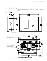
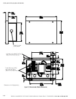
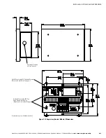
5.2
Installing Distributed Bypass Control Wiring
NOTE
When installing external wiring to the Powerware Hot Sync CAN Bridge Card, conduit must be
installed to the UPS cabinet. When installing internal wiring to the Powerware Hot Sync CAN Bridge Card
terminals, route the wiring through the internal opening in the X-Slot communication bay.
NOTE
When installing interface wiring for the pull chain, conduit must be installed between UPSs.
To install distributed bypass control wiring:
1.
Verify the UPS system is turned off and all power sources are removed. See
Chapter 7, “UPS Operating Instructions,” for shutdown instructions.
2.
Perform the procedure listed in paragraph 5.1.
3.
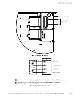
Terminal block TB3 is accessible on the left side of the X-Slot communication bay
(see Figure 4‐21). To gain access to terminal block TB1, TB2, and the left
interface entry conduit landing plates, remove the screws securing the top
internal safety shield panel and remove the panel. Retain the hardware for later
use.
4.
Remove the interface entry conduit landing plates to drill or punch holes (see
Figure 4‐16).
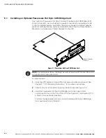
5.
Reinstall the interface entry plates and install the conduit.
6.
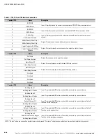
To locate the appropriate terminals and review the wiring and termination
requirements, see paragraph 3.2.4, Table 4‐1,
through
7.
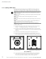
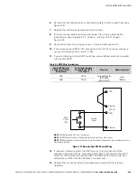
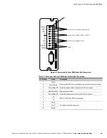
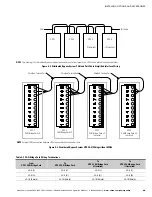
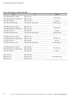
Route and install CAN wiring between the UPS cabinets. See Figure 5‐2 and
Table 5‐1 for the Powerware Hot Sync CAN Bridge Card terminal location and
Figure 5‐3, Figure 5‐4, and Table 5‐2 for wiring information.
8.
If a tie cabinet with Module Output Breakers (MOBs) is being wired, proceed to
Step 11; otherwise, proceed to Step 9.
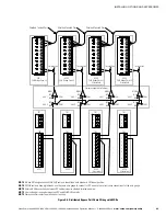
9.
Route and install distributed bypass system pull-chain wiring between the UPS
cabinets. See Figure 5‐5 and Table 5‐3 for wiring information.
10.
11.
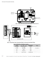
Route and install distributed bypass system pull-chain wiring between the UPS
cabinets and tie cabinet MOBs. See Figure 5‐6 and Table 5‐4 for wiring
information.
NOTE
Setup of the Powerware Hot Sync CAN Bridge Card for parallel operation must be performed by an
authorized Eaton Customer Service Engineer. Contact an Eaton service representative to schedule a date.
12.
Reinstall the top internal safety shield panel and secure with the retained
hardware.
13.
Close the door and secure the latch.
Summary of Contents for Power Xpert 9395P-1200
Page 195: ......
Page 196: ... P 1640005004 P 164000500 4 ...


