Capitole 40
1991.901 G01 002 39
2.2.3.2
Removable version
Bottom cable-entry for large incoming feeders is realised
via a bottom plate of insulation material.
As an alternative, the bottom inlet may be sealed with foam
plastic.
The cables are directly connected to the equipment.
Strips for cable support and strain relieve are available.
Large incoming feeders with "top-entry" do have bare -
terminals protruding from the top of the cubicle.
Cables to incoming and outgoing units can enter the cable
compartment, by top or bottom. For this purpose, the
"ceiling" and the "bottom" of the cable compartment have
removable steel gland plates. Cables with "bottom entry"
may be sealed with foam plastic.
The LH-side wall of the cable compartment is provided with
4 strips for cable support and fixation of the cables, see
Figure 2-60.
In case of a TNS system with 3 -pole switching devices, the
neutral busbar and the PE busbar are located on the LH
side wall of the cable compartment ( in case of a 4 -pole
switching devices the neutral busbar is not located in the
cable compartment, but integrated in the vertical
distribution busbar system ). In case of a TNC system the
cable compartment is only fitted with a PEN busbar.
For cable connection the busbar(s) in the cable
compartment are fitted with threaded holes M6 fore
outgoing units up to 160 Amps. Above 160 Amps a
connection plate for a bolt M10 issued.
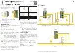
A: fixation with cable clamps
B: fixation with cable glands
Figure 2-60: Fixation of cables on the support strips
M10 bolt and
connection plate
for over 160
M6 screw for up
to 160 A
Summary of Contents for Holec Capitole 40
Page 2: ...Administrative data Issue number G01 002 Date of issue 30 09 2008...
Page 62: ...Capitole 40 62 1991 901 G01 002 Place the draw out units into position Figure 3 35...
Page 74: ...Capitole 40 74 1991 901 G01 002 Figure 4 1...
Page 76: ...Capitole 40 76 1991 901 G01 002 Figure 4 2...
Page 78: ...Capitole 40 78 1991 901 G01 002 Figure 4 3...
Page 82: ...Capitole 40 82 1991 901 G01 002 Figure 4 5 Figure 4 6...
Page 84: ...Capitole 40 84 1991 901 G01 002 Figure 4 7...
Page 86: ...Capitole 40 86 1991 901 G01 002 Figure 4 8...
Page 88: ...Capitole 40 88 1991 901 G01 002 Figure 4 9...
Page 90: ...Capitole 40 90 1991 901 G01 002 Figure 4 10...
Page 92: ...Capitole 40 92 1991 901 G01 002 Figure 4 11...
Page 94: ...Capitole 40 94 1991 901 G01 002 Figure 4 12...
Page 96: ...Capitole 40 96 1991 901 G01 002 Figure 4 13...
Page 97: ...Capitole 40 1991 901 G01 002 97 APPENDIX 1 EU DECLARATION OF CONFORMITY...
Page 98: ...Capitole 40 98 1991 901 G01 002 APPENDIX 2 KEMA TEST REPORT...
Page 99: ...Capitole 40 1991 901 G01 002 99...
Page 100: ...Capitole 40 100 1991 901 G01 002 APPENDIX 3 LLOYD S CERTIFICATE...
Page 101: ...Capitole 40 1991 901 G01 002 101...


