background image

3

COMPASS SIT-TO-STAND INSTALLATION MANUAL

         Eaton.com/compass

Compass sit-to-stand

Installation Manual 

•   

Read and understand the instruction herein before attempting to 

unpack, assemble, operate or service the sit-to-stand desk�

• 

 Follow all information that is found on safety labels on the product 

and packaging�

•   

Familiarize yourself with the various console components 

described within this manual�

•   

The use of personal protective equipment such as safety glasses, 

work gloves and steel toed shoes are recommended during the 

unpacking and set-up of the desk�

• 

 Read, understand and follow the guidelines and limitations herein 

for loading your desk�

• 

 Familiarize yourself with the warning symbols that appear 

throughout this manual�

Before You Begin  

Before installing Eaton’s Compass sit-to-stand desk, it is recommended that you do the following:

DANGER

DANGER indicates a hazardous situation which, if not avoided, will 

result in death or serious injury�

WARNING

WARNING indicates a hazardous situation which, if not avoided, 

could result in death or serious injury�

CAUTION

CAUTION indicates a hazardous situation which, if not avoided, could 

result in minor or moderate injury�

NOTICE

NOTICE is used to address practices not related to physical injury�


Important Safety Instructions

DANGER Read all instructions before assembling and using this furnishing - Save these instructions

WARNING


WARNING

 – To reduce the risk of electric shock: This desk includes one power cord� Always fully unplug this desk from the electrical 

outlets before cleaning, testing, repairing or moving the desk�

CAUTION


  1�   This desk is for commercial use only�

  2�  Unplug from outlet before putting on or taking off parts� NOTE: 

This console includes one power cord�

  3�  Close supervision is necessary when this furnishing is used 

by, or near children, invalids, or disabled persons�

  4�  Use this furnishing only for its intended use as described in 

these instructions� Do not use attachments not recommended 

by the manufacturer�

  5�  


Never operate this furnishing if it has a damaged cord or 

plug, if it is not working properly, if it has been dropped or 

damaged, or has become wet� Return the furnishing to a 

service center for examination and repair�

  6� Keep the cord(s) away from heated surfaces�

  7�   Never operate the furnishing with the air openings blocked� 

Keep the air openings free of lint, hair, and the like�

  8� Never drop or insert any object into any opening�

  9� Do not use outdoors�

10� 

 WARNING: Risk of Electric Shock – Connect this 

furnishing to properly grounded outlets only�  See 

grounding instructions�

11�   To disconnect, turn all controls to the off position, then remove 

plugs from outlets�

12�  To reduce risk of electrical shock, this furnishing has polarized 

plugs (one blade wider than the other)� These plugs will fit into 

polarized outlets only one way� If a plug does not fit fully into 

the outlet, reverse the plug� If it still does not fit, contact a 

qualified electrician to install the proper outlet� Do not change 

the plug in any way�

13�  CAUTION: Pinch Point - DO NOT, UNDER ANY 

CIRCUMSTANCE, PLACE A BODY PART IN THE 

PATH OF THE WORKSURFACE WHILE IT IS BEING 

LOWERED� DO NOT PLACE ANY OBJECT ON TOP 

OF THE DESK’S THAT COULD INTERFERE WITH 

THE TRAVEL OF THE WORKSURFACE�

This desk has an electrically driven adjustable worksurface� The 

desk’s lift motors have sensors that will detect an obstruction 

when moving downward� When an obstruction is sensed, the 

worksurface will automatically begin to raise�

14�  Installation and assembly must be performed by qualified 

personnel�

15�  Ensure that the floor is able to withstand the weight of the 

console when fully loaded�

16�  Ensure the desk is plumb and level for proper operation� Route 

all power cords and cabling as instructed, away from any 

possible pinch points or moving parts�

17�  To reduce risk of personal injury and product damage, always 

ensure a sufficient amount of personnel are present when 

unpacking, moving and assembling the desk system�

Failure to adhere to these warnings may result in serious 

injury or property damage.

Summary of Contents for Compass sit-to-stand

Page 1: ...Compass sit to stand Modular Office Furniture Compass sit to stand STS powered adjustable height modular office furniture system Installation manual...

Page 2: ...aton 160 Gold Star Boulevard Worcester MA 01606 Email InfoESWorcesterMA Eaton com Web Visit us at Eaton com CompassSTS and click on Contact Us Complete and submit the form as directed on our website D...

Page 3: ...tions Do not use attachments not recommended by the manufacturer 5 Never operate this furnishing if it has a damaged cord or plug if it is not working properly if it has been dropped or damaged or has...

Page 4: ...mpass furniture desks When it is not possible to attach linear sit to stand desk the maximum allowable organizer wall panel height is 20 Lateral 20 Lb Force Max Organizer wall panel max 20 Linear inte...

Page 5: ...SS SIT TO STAND INSTALLATION MANUAL Eaton com compass SECTION II Parts Identification Free Standing Linear Type Cable Grommet Lift Column Control Box Worksurface Support Control Pad Warning Labels Wor...

Page 6: ...Manual COMPASS SIT TO STAND INSTALLATION MANUAL Eaton com compass Free Standing Corner Type Cable Grommet Lift Column Control Pad Control Box Worksurface Support Warning Labels Worksurface Cable Fill...

Page 7: ...STAND INSTALLATION MANUAL Eaton com compass Integrated Linear Type Cable Grommet Upper Lift Bracket Lift Bracket and Cover Lift Column Control Box Worksurface Support Control Pad Back Panel Stretcher...

Page 8: ...L Eaton com compass Integrated Corner Type Cable Grommet Lift Column Control Pad Filler Strip Back Panel Stretcher Worksurface Support Worksurface Bracket Corner Foot Control Box Worksurface Levelers...

Page 9: ...head screw silver D M6 x 10mm Phillip s head screw black E 8 x 3 4 Phillips flat head wood screw black F 1 4 x 3 4 hex washer head screw black G 1 4 20 x 3 8 button head screw H 8 32 x 1 4 Phillips he...

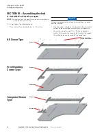
Page 10: ...ect finished laminate surface from scratches or other possible damage Align the support and bracket if required to the worksurface using the holes pre drilled in worksurface for alignment Secure the s...

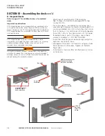
Page 11: ...ift columns closest to control box Remove plastic filler strip from worksurface Route cable from lift column through work surface pathway into support and along the stiffener to control box area Repla...

Page 12: ...using 4 M6 x 20 Phillips Head screw C and 5 16 lock washers K per lift Use a 3 Phillips bit Ends of feet will be approximately even with the back edge of worksurface and offset from the front user sid...

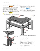
Page 13: ...annel tab To retain tab in slot assemble inner channel section over tab attach using 2 20 acorn nuts I Do not tighten Side outer channel down to top of foot aligning tab in outer channel and slot in f...

Page 14: ...ys ensure a sufficient amount of personnel are present during the assembly process Attach legs to existing units if there are any See Compass Installation Guide page 25 for leg connection info For cor...

Page 15: ...bracket cover secured by magnetic fasteners Assemble lift columns to leg assemblies using 3 1 4 20 x hex head screws F each column Check that all parts are properly seated in position and tighten all...

Page 16: ...otor housing No lock washers are used Use a 3 Phillips bit DO NOT TIGHTEN SCREWS NOTICE Start all screws in their holes before tightening NOTE In certain cases some bolts may be difficult to access Th...

Page 17: ...and visually verify to avoid pinching any previously installed cables Secure with 2 1 4 20 locking nut J to stud end Secure with 4 M6 x 10 Phillips head screws D into lift motor housing No lock washer...

Page 18: ...E PRECEDING ASSEMBLY STEPS HAVE BEEN FOLLOWED AND ARE COMPLETED VERIFY THE CORRECT POSITION OF ALL LIFT MOTOR CONNECTORS VERIFY THAT ALL LIFT MOTOR CABLES ARE PROPERLY SEATED IN THEIR RECEPTACLES MAKE...

Page 19: ...ultiple attempts see SECTION IV C for initialization of the lift system If not all of the lift motors respond remove the AC power Disconnect the motor cable both ends of the lift motor that is out of...

Page 20: ...l Every six months Visually inspect the product looking for loose fasteners and loose or damaged parts Inspect all wires and cables looking for loose connections and pinched or frayed wires Laminated...

Reviews: