14
Compass sit-to-stand
Installation Manual
COMPASS SIT-TO-STAND INSTALLATION MANUAL
Eaton.com/compass
SECTION III – Assembling the desk
cont’d.
D. Integrated Desks
Refer to pages 6-7 for additional views of completed
desks
Important considerations
STS Integrated desks are intended to be assembled in-line
with, and connected to, other Compass STS or stationary
desks� The legs of the STS Integrated desk bolt to additional
STS Integrated desks or standard stationary desks to form a
unitized structure�
WARNING
STS Integrated desks are not intended to be used in
conjunction with upper Compass accessories, i�e�, shelving
and/or overhead storage� Doing so may cause risk of
personal injury and product damage�
WARNING
During the assembly process, components may become
unstable� To reduce the risk of personal injury and product
damage, always ensure a sufficient amount of personnel are
present during the assembly process�
•
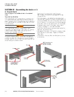
Attach legs to existing units if there are any�
See Compass Installation Guide page 25 for leg
connection info�
•
For corner desks – assemble the corner leg post
assembly per Compass Installation Guide page 20� It
can be assembled LH or RH� Attach the short corner
foot to the post� LH and RH are not interchangeable�
•
Install (3)
1
⁄
4
-20 x ¾" hex head screws (F) into upper
threaded holes in each of the Legs� Leave these
screws protruding
3
/
8
" – DO NOT TIGHTEN�
•
Install the stretcher panels between legs using the
keyholes� Leave bolts loose
•
Add upper lift brackets in 3 locations using key holes�
Note orientation of brackets� Tighten all the bolts
finger tight�
•
Install plastic top caps (M) and other plastics covers
as necessary�
1
⁄
4
-20 x .75
Hex head
screws (3)
per leg
Key holes
Stretcher panels
Corner leg
assembly
NOTE: Plastic covers for
channels not shown,
remove as necessary
Leg assembly
Short corner
foot assembly
Upper lift brackets
Note left / right
hand orientation


