17
Compass sit-to-stand
Installation Manual
COMPASS SIT-TO-STAND INSTALLATION MANUAL
Eaton.com/compass
SECTION III – Assembling the desk
cont’d.
Assembly of 72" integrated corner desk
NOTE:
Assemble desk frame, lift columns and main
worksurface as noted in previous pages�
WARNING
During the assembly process, components may become
unstable� To reduce the risk of personal injury and product
damage, always ensure a sufficient amount of personnel are
present during the assembly process�
•
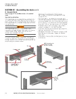
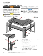
Assemble 72" extension worksurface support to main
worksurface support via 2 threaded studs� Carefully guide
the lift motor housing over the lift motor on opposite end�
CAUTION
Pinched electrical cables may cause risk of electrical
shock or equipment damage� Use care and visually verify
to avoid pinching any previously installed cables�
•
Secure with (2)
1
⁄
4
"-20 locking nut (J) to stud end�
•
Secure with (4) M6 x 10 Phillips head screws (D) into
lift motor housing. No lock washers are used. Use a #3
Phillips bit� DO NOT TIGHTEN SCREWS�
•
Assemble 72" extension worksurface to worksurface
support using #10 x 1" Phillips head screws (A).
•
Install worksurface tie plates as shown, using (8) #10 x 1"
Phillips head screws (A) each�
•
Route all lift cables through the support structure as
shown on page10�
•
After all lift motors are assembled, place desk assembly in
final location and level�
•
Connect AC cord to AC outlet�
•
Initialize lift system - per page 18�
•
Cycle lift system to 18" twice�
•
Tighten all lift motor screws�
Install Cable Chain Kit
•
See page 16�
M6 x 10 screws
(4) Per lift column
72" Extension
support
Lift
Column
Tie plates
#10 x 1"
wood screws
Pre-assembled
worksurface
with cabling
1
⁄
4
"-20 Locking
Nut (2)
Main support
studs
Extension
worksurface


