25
Instruction Booklet
IB 52-01-TE
Effective October 2010
Instructions for the Eaton Type CM52
Network Protectors 800 to 4500 Amperes
EATON COrPOrATION www.eaton.com
25 IB -52-01-TE
Effective 11/05/08 (super cedes 11/19/03) IB 52-01-TE
25
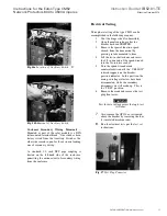
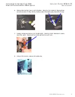
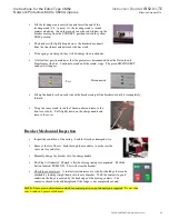
26. Loosen Front Bracket plates to set the claw position.
28. The next step is to convert the door hinge position. Close the door of the Network Protector
and tighten down all hold down bolts, then remove the hinge pin and covert it to the right hand
side. This completes the conversion of the Network Protector.
RH Side Shown
This claw engages the wire form that
runs through the breaker element.
This claw trips the breaker when the
external handle is placed in the open
position. The claw must be positioned
correctly. Loosing the front brack et
plates will allow some horizontal
adjustment to clear the breaker
element and set the claw properly.
After setting, check clearance by
slowly pushing the breaker element in
position and watch engagement of the
wire form. If clearan ce is ok, rack the
break er into the connect position.
With the handle in “Auto”, manually
charg e the break er and close it with
the push button, if the break er trips
free, then the claw must be adjusted to
back o ff the wire form position.
Front Bracket
Adjustment

