30
Instruction Booklet
IB 52-01-TE
Effective October 2010
Instructions for the Eaton Type CM52
Network Protectors 800 to 4500 Amperes
EATON COrPOrATION www.eaton.com
30 IB -52-01-TE
Effective 11/05/08 (super cedes 11/19/03) IB 52-01-TE
•
Push the button labeled “PUSH OFF”. The breaker will OPEN.The main and arc contacts should
only be dressed with fine scotch bright if there is black carbon residue from arcing. Do not use a
file on the contacts.
If the contacts are pitted then the contact can be tested fo r low resistance. The breaker will have to
be closed again. The Ductor leads will have to be applied from contact cluster to contact cluster.
The Ductor maximum reading should be 35 Micro Ohms or below.
Electrical Testing
•
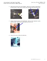
Replace the breaker cov er by slightly pushing down on the charging handle and inserting the
handle through the cover slot. Tighten the bolts using a cross tighten pattern.
•
With the breaker in the open position, push the breaker toward the cell until it stops
.
MAKE SURE THAT THE BREAKER IS PUSHED ALL THE WAY IN. A PARTIAL INSERTION
WILL DAMAGE THE SHELF WHEN BEING CRANKED BACK IN.
•
Crank the break er until the yellow window is filled. This is the
TEST position.
•
The test set ground leads must always b e conn ected first. Bond
the latch shutter of the break er to ground.
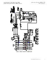
TEST SWITCH (PHASING BLOCK)
CAUTION Test for zero voltage on the potential studs on the test switch per below:
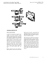
Connect Test Kit Leads N1,N2,N3 (Black cov ers) and T1,T2,T3 (Blue covers) on th e studs o f the test
block.
•
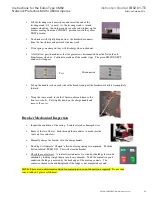
Remove the dead front upper compartment cover.
Connect the Power Leads (Red Covers) o f the Test kit
to the energized network bus. Make sure that these
leads are the ones that have the in line fuse.
Network Side
Transformer Side
CT Jacks
Using a Multi-Meter, check
for voltage on the labeled N1,
N2, N3, T1, T2, T3 stud
positions. Verify ZERO volts
present


