22
Instruction Booklet
IB 52-01-TE
Effective October 2010
Instructions for the Eaton Type CM52
Network Protectors 800 to 4500 Amperes
EATON COrPOrATION www.eaton.com
22 IB -52-01-TE
Effective 11/05/08 (super cedes 11/19/03) IB 52-01-TE
22
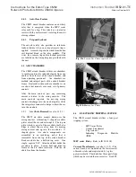
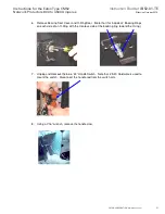
9. Remove shaft assembly from the side of the cassette
10. Remove Right Hand mounting bracket from the blue “43” switch and install the Left Hand
Bracket (provided in handle conversion kit onto the existing switch).
11. Rotate the switch lever 180 degrees and rotate the handle claw as shown.
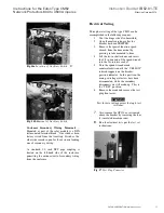
12. On the Left Hand side of the unit, remove the solid handle bearing cover and gasket and
reinstall on the now open Right Hand side outlet.
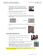
13. Remove upper fuse barrier and inter-phase barriers.
14. Remove the (2) .25-20 Barrier Hold down bolts and slide entire barrier assembly out of
the unit.
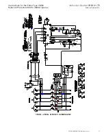
15. Cut wire ties and remove the electrical interlock assembly. This will also have to be
transferred to the opening side of the enclosure. Cut wire ties to red harness and route
the red wire connection bundle to the left side of the cassette.
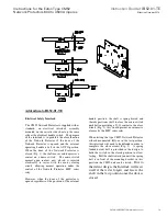
16. The existing electrical interlock assembly will have to be disassembled and re-assembled
in reverse order for the Left Hand Side.
Barriers are set into a notch
on the cross channel and
must be lifted up to clear.
Left Hand
Right Hand


