23
Instruction Booklet
IB 52-01-TE
Effective October 2010
Instructions for the Eaton Type CM52
Network Protectors 800 to 4500 Amperes
EATON COrPOrATION www.eaton.com
23 IB -52-01-TE
Effective 11/05/08 (super cedes 11/19/03) IB 52-01-TE
23
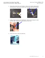
17. Remove (2) spring Nuts that hold the switch bracket in the “U” channel by Pushing down
and turning to lift out of the Right Hand channel. Transfer the nuts into the Left Hand
Channel.
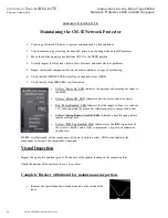
18. Move handle shaft and put shaft through the alignment hole. Install backing rings and O-
rings on shaft in the proper order. Refer to step 7.
19. Install bearing Seal Cover.
20. Mount Switch and connect linkage to handle.
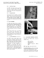
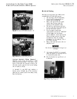
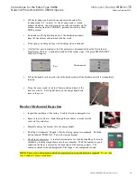
21. Final switch installation should appear as shown below.
22. Install Left Hand handle spring provided in handle conversion kit on shaft outside of tank.
Note: Existing switch
lever reversed 180
degrees for LH
installation.

