background image

12

Instruction Booklet 

IB 52-01-TE

Effective October 2010

Instructions for the Eaton Type CM52

Network Protectors 800 to 4500 Amperes

EATON COrPOrATION www.eaton.com

12                                                                                                                                                                                            IB -52-01-TE 

 
Effective 11/05/08 (super cedes 11/19/03) IB 52-01-TE                                                                                                              


12


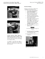
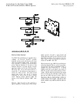
Fig. 18


Test plug with connections


CAUTION


THE NETWORK SIDE BUS WILL BE 

ENERGIZED.   

ATTACH THE TEST KIT SUPPLY LEADS 
USING SUITABLE INSULATED GLOVES. 


* Alternative Test position with visible break 
available with ex tended jumpers. 


MANUAL CLOSING OF THE CM52 
BREAKER 

 
With the breaker racked out on its rails, the 
CM52 breaker can be manu ally closed (fo r 
maintenance purposes only). 


WARNING  

DO NOT ATTEMPT TO MANUALLY 

CLOSE A CM52 BREAKER ON TO AN 

ENERGIZED SYSTEM.


RENEWAL PARTS 


The  CM52  breaker  modular  construction  makes  
change  out  o f  replacement  p arts  an  easier  task  
than on other network breakers. 
 
The following list tabulates the ren ewal parts  for 
the type CM52 breaker: 
 

1.  Motor Assembly 125 VAC 
2.  Indicating  Diagnostic Module (IDM) 
3.  Spring Release 125 VAC 
4.  Trip actuator 
5.  Auxiliary Switch 

a.  Position A (brkr use only) L/H 

rear 

b.  Position  D-4  form  C  R/H  (std 

on all units) 

6.  BF1 Motor closing relay 
7.  BF2 Anti-close relay 
8.  Current Transform er 
9.  Control  Power  Transfo rmer  (480V 

only) 

10.  480V  Relay  Potential  Trans form er 

(480V only) 

11.  15A C.L. Fuses 
12.  Lifting Brack ets 
13.  Lever-in Crank w/10mm Socket 
14.  Arc Chute Assembly 
15.  Test Switch. 


Grasp the manually charging handle and pull 
downward. Repeat this operation until the Spring 
Indicator shows that the charging springs have 
 
 been charg es.  Push the GREEN “ ON” 
pushbutton.  The breaker should close and the 
break er semaphore should indicate, “CLOSE” 


To manually open a CM52 breaker, during 
maintenance, push the RED “ OFF” pushbutton.  
The breaker should open and the breaker 
semaphore should indicate “TRIP”. 


Summary of Contents for CM52

Page 1: ...Network Protector See important disclaimer of warranties and limitation of liability on page ii See important safety information on page iii and iv Effective October 2010 Supersedes November 2008 Instruction Booklet IB 52 01 TE Instructions for the Eaton Type CM52 Network Protectors 800 to 4500 Amperes ...

Page 2: ...ould be consulted NO WARRANTIES EXPRESSED OR IMPLIED INCLUDING WARRANTIES OF FITNESS FOR A PARTICULAR PURPOSE OR MERCHANTABILITY OR WARRANTIES ARISING FROM COURSE OF DEALING OR USAGE OF TRADE ARE MADE REGARDING THE INFORMATION RECOMMENDATIONS DESCRIPTIONS AND SAFETY NOTATIONS CONTAINED HEREIN In no event will Cutler Hammer be responsible to the user in contract in tort including negligence strict ...

Page 3: ...te areas of the instruction bookfor further i nstructions 1 CM52 Networ k protectors are designed to operate within the current and voltage limitations given on their nameplates DO NOT applies these units to systems with currents and or voltages exceeding these limits See Tables 1 and 2 2 To perform work on this type of equipment requires personnel with traini ng and experience i n high voltage ci...

Page 4: ...aton corporation www eaton com iv IB 52 01 TE Effective 11 05 08 super cedes 11 19 03 IB 52 01 TE iv CAUTION The network protectors described in this book were designed and tested to operate within their nameplate ratings Operation outside of these ratings may cause the equipment to fail resulting in bodily injury and property damage ...

Page 5: ...III Operation 3 1 Procedure to Remove the Drawout Unit 4 3 1 1 To Open the Door 4 3 1 2 Levering the Breaker 4 3 2 Enclosure 5 3 2 1 Outside Operating Handle 5 3 2 2 Mechanical Anti CloseInterlock 6 3 2 3 Installing Network Protectors to Network Transformer 6 Section IV CircuitBreaker Descriptionand Operation 4 1 Introduction 6 4 2 BasicCircuitBreaker Assembly 6 4 3 Pole Unit 7 4 3 1 Primary Movin...

Page 6: ...2 Enclosure 1 3 NPL Fuse Housing External fuses 2 3a NPL Fuse Housing Internal fuses 2 4 CM52 w BreakerElement withdrawn on rails 3 5 Arc Chute 3 6 Relay Module Panel Opened 4 7 Inserting Levering In Crank 4 8a Breaker in Connect position 5 8b Breaker in Test position 5 8c Breaker in Disconnect Position 5 9a Handle in OPEN 6 9b Handle in AUTO 6 9c Handle in CLOSE 6 10 CM52 with Breaker withdrawn 6...

Page 7: ...Units Continuous Current Rating Amps Breaker Element Width CM52 Interrupting Rating kA CM52 Close and Latch Rating kA IEEE ANSI Interrupting Rating kA IEEE ANSI Close and Latch Rating kA 800 17 42 35 30 25 1200 17 42 35 30 25 1600 1875 17 42 35 30 25 2000 17 42 35 35 35 2250 22 65 45 60 40 2500 2825 22 65 45 60 40 3000 22 65 45 60 40 3500 35 85 65 60 40 4500 35 85 65 60 40 Amperage Rating CM52 Bre...

Page 8: ...s for the EatonType CM52 Network Protectors 800 to 4500 Amperes eaton corporation www eaton com viii IB 52 01 TE Effective 11 05 08 super cedes 11 19 03 IB 52 01 TE viii Fig 1 CM52 800A 2000A Network Protector Fig 1A 3500A 4500A Network Protector NOTE 2250A 3000A Not Shown ...

Page 9: ...m are commonly used in such areas of high load density as metropolitan and suburban business districts When a fault on a primary system cable or network transformer occurs the CM52 Network Protectors will open to isolate the fault from the network system Loss of the feeder will not result in service outage to any load on the secondary network The other primary feeders will carry the load until the...

Page 10: ...ctober 2010 Instructions for the EatonType CM52 Network Protectors 800 to 4500 Amperes eaton corporation www eaton com Technical Data Effective August 1999 Page 24 TD 52 01A T E Spot Network Systems Cutler Hammer This page intentionally left blank ...

Page 11: ...placed in storage for more than a few weeks it should be inspected and tested thoroughly and any deficiencies reported 1 2 HANDLING 1 2 1 Lifting of Breaker To facilitate lifting two lifting brackets are supplied and mounted inside the door of each enclosure These brackets can only be attached once the breaker has been completely withdrawn on its extension rails 1 2 2 Lifting the Enclosure A SPREA...

Page 12: ...ts 480Y 277 volts at 60 Hertz with other voltages as well as 50 Hertz units available upon request CAUTION Type CM52 Network Protectors are protective devices As such they are maximum current rated devices Therefore they should not under any circumstances be applied outside of their ratings which could cause the equipment to fail resulting in severe personal injury death or property damage Fig 3 N...

Page 13: ...s contact system current transformers primary and secondary disconnect 2 1 2 1 Arc chutes Arc Chutes are designed and constructed to entrap the splitter plates A single captive hold down screw is located in the rear of each arc chute to facilitate its removal Fig 5 Arc Chute 2 1 2 2 Current Transformers Current transformers located on the rear of the circuit breaker and are molded frame constructi...

Page 14: ...OVE THE DRAWOUT UNIT FROM HOUSING When the enclosure is not attached to a transformer the enclosure must be supported in a way that will prevent tipping forward when the door is open and the draw out unit is on the extension rails 3 1 1 To Open Door Loosening all the bolts starting with the bolts on the hinged side opens the quick opening enclosure The bolts are loosened until the bolts are comple...

Page 15: ...handle is made watertight through the enclosure by use of an O ring held captive with a retaining plate 3 2 1 Outside Operating Handle WARNING DO NOT MANUALLY CLOSE A PROTECTOR TO CONNECT AN ENERGIZED TRANSFORMER TO AN ENERGIZED NETWORK SYSTEM The operating handle has three positions OPEN AUTO and CLOSE as indicated on the nameplate located directly beside the handle The handle is held captive in ...

Page 16: ...ch permits an operator to open the enclosure door while the breaker remains closed This entire anti close assembly is located on the cassette and can be reversed for either left hand or right hand door hinging 3 2 3 Installing Network Protector to Network Transformer 1 Remove front fuse cover barrier cover 2 Remove fuse links or internal fuses 3 Remove Interphase barriers by lifting barrier up and...

Page 17: ... one primary contact assembly which consists of a moving portion 4 3 1 Primary Moving Contacts Depending upon the frame size each primary moving contact assembly is comprised of multiple individual copper contact fingers connected to the load conductor through flexible braided connectors Two flexible connectors are used to connect each finger to the load conductor The number of fingers used depend...

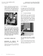
Page 18: ...rically operated circuit breakers can also be manually closed and opened through the use of the front mounted charging handle and Manual ON buttons and Manual OFF buttons An electrically operated circuit breaker from the factory is also equipped as standard with a spring release to close the circuit breaker electrically A low energy trip activator is supplied to open breaker 4 4 1 Procedure to rem...

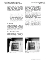
Page 19: ...ning current is driven to the arcing contacts The main contacts separate the moving arcing contacts discharge into the arc chute plates while the integral arc runner also helps to draw the arc into the arc chute 4 5 1 Arc Chute Removal see also 2 1 2 1 The CM52 arc chute mounts down over the arcing contact Alternating V shaped arc chute plates attract the arc and interrupt it The top arc plate whi...

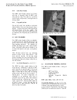
Page 20: ...t of the breaker provides voltage regulation and diagnostic information The IDM has self diagnostic circuitry built into the design to aid the user in determining if a component should be replaced The LED indicators are described below MOTOR ENABLED Red LED Indicates the supply voltage is normal and the motor circuit is operable POWER ON Yellow LED Indicates the presence of normal power input to t...

Page 21: ...e testing of the type CM52 can be accomplished in the following manner 1 Vent the hinge side if submersible 2 Open the enclosure door after the breaker has been TRIPPED 3 Remove the special function speed wrench from the door mount by pressing in tabs mounted to door 4 Lift the lev in shutter door and insert the 3 8 square end of the speed wrench into the lev in drive socket 5 Turn the speed wrenc...

Page 22: ... easier task than on other network breakers The following list tabulates the renewal parts for the type CM52 breaker 1 Motor Assembly 125 VAC 2 Indicating Diagnostic Module IDM 3 Spring Release 125 VAC 4 Trip actuator 5 Auxiliary Switch a Position A brkr use only L H rear b Position D 4 form C R H std on all units 6 BF1 Motor closing relay 7 BF2 Anti close relay 8 Current Transformer 9 Control Pow...

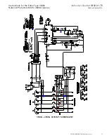
Page 23: ... TE Effective October 2010 Instructions for the EatonType CM52 Network Protectors 800 to 4500 Amperes eaton corporation www eaton com 13 IB 52 01 TE Effective 11 05 08 super cedes 11 19 03 IB 52 01 TE 13 800A 2000A 216Y 125 SCHEMATIC ...

Page 24: ... TE Effective October 2010 Instructions for the EatonType CM52 Network Protectors 800 to 4500 Amperes eaton corporation www eaton com 14 IB 52 01 TE Effective 11 05 08 super cedes 11 19 03 IB 52 01 TE 14 800A 2000A 480 277 SCHEMATIC ...

Page 25: ...TE Effective October 2010 Instructions for the EatonType CM52 Network Protectors 800 to 4500 Amperes eaton corporation www eaton com 15 IB 52 01 TE Effective 11 05 08 super cedes 11 19 03 IB 52 01 TE 15 2250A 3000A 216Y 125 SCHEMATIC ...

Page 26: ...TE Effective October 2010 Instructions for the EatonType CM52 Network Protectors 800 to 4500 Amperes eaton corporation www eaton com 16 IB 52 01 TE Effective 11 05 08 super cedes 11 19 03 IB 52 01 TE 16 2250A 3000A 480Y 277 SCHEMATIC ...

Page 27: ...TE Effective October 2010 Instructions for the EatonType CM52 Network Protectors 800 to 4500 Amperes eaton corporation www eaton com 17 IB 52 01 TE Effective 11 05 08 super cedes 11 19 03 IB 52 01 TE 17 3500A 4500A 216Y 125 SCHEMATIC ...

Page 28: ...TE Effective October 2010 Instructions for the EatonType CM52 Network Protectors 800 to 4500 Amperes eaton corporation www eaton com 18 IB 52 01 TE Effective 11 05 08 super cedes 11 19 03 IB 52 01 TE 18 3500A 4500A 480Y 277 SCHEMATIC ...

Page 29: ...rted electrically in series with the motor closing circuit allowing normal operation under the control of the Network Protector MPC series relay However when the door of the protector is opened regardless of the position of the external handle position the shaft is spring biased and thereby positions itself to clear the micro switch pushbutton providing a N O contact in the close circuit Fig 2 thi...

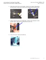
Page 30: ...und open bus work Please read instructions completely before beginning handle reversal 1 Move the Handle to the OPEN position and withdraw and remove the breaker element to allow access to the interior of the unit 2 Move the Handle back to the AUTO position after the breaker is removed to facilitate removal of the handle 3 Discharge the handle return spring using a screwdriver as shown CAUTION The...

Page 31: ...08 super cedes 11 19 03 IB 52 01 TE 21 6 Remove Bearing Seal Cover and O Ring Seal Note that this includes 2 Backing Rings on each side of an O Ring with the Concave side of the backing ring toward the O ring 7 Unplug and Remove the blue 43 Handle Switch Note that 25 20 Hardware is used to mount the switch Disconnect the handle rod from the switch arm 8 Using a 7 16 wrench remove the handle claw ...

Page 32: ...ide of the unit remove the solid handle bearing cover and gasket and reinstall on the now open Right Hand side outlet 13 Remove upper fuse barrier and inter phase barriers 14 Remove the 2 25 20 Barrier Hold down bolts and slide entire barrier assembly out of the unit 15 Cut wire ties and remove the electrical interlock assembly This will also have to be transferred to the opening side of the enclo...

Page 33: ...turning to lift out of the Right Hand channel Transfer the nuts into the Left Hand Channel 18 Move handle shaft and put shaft through the alignment hole Install backing rings and O rings on shaft in the proper order Refer to step 7 19 Install bearing Seal Cover 20 Mount Switch and connect linkage to handle 21 Final switch installation should appear as shown below 22 Install Left Hand handle spring...

Page 34: ...er cedes 11 19 03 IB 52 01 TE 24 23 Hook spring on handle ear and Network Protector bracket 24 Rotate the handle to AUTO position while applying inward pressure CAUTION This step winds the spring under compression and has considerable stored energy Use caution when installing the assembly 25 It is recommended to use a pair of Vice Grip Pliers to hold the handle in place while installing the setscr...

Page 35: ...ork Protector RH Side Shown This claw engages the wire form that runs through the breaker element This claw trips the breaker when the external handle is placed in the open position The claw must be positioned correctly Loosing the front bracket plates will allow some horizontal adjustment to clear the breaker element and set the claw properly After setting check clearance by slowly pushing the br...

Page 36: ... Right 800 2000A CM52 Hardware Bag 680C602G09 InterlockBracket NEA7021H03 L H NEA7021H03 R H Handle Spring NEB7024H02 R H NEB7024H01 L H Handle Indicator Drive Pins 70012ABH1S Qty 2 Qty 12 38 X 3 25 Bolt 70100EG07X Possible CARTE XFRM Flex Conn Qty 12 531 Washer 0801975H46 Transformer Qty 12 38 Washer 0801986H16 Flex Conn Qty 2 Spacer 5765A38H01 Kicker Bracket Qty 4 531 ID washer 08019725H24 Kicke...

Page 37: ... 70100EG0CR Transformer Qty 12 50 X 3 25 Bolt 70100EG07X Possible Carte XFMR Conn Qty 50 50 13 Lock 70510CV10S Transformer Kicker Brackets Qty 12 50 Washer 70500BD31F Flex Conn Qty 2 50 X 2 Bolt 70100EG0CV Kicker Bracket Qty 12 531 Washer 0801975H46 Transformer Qty 2 50 13 Nut 70210BT61E Kicker Bracket Qty 38 50 13 Lock 70510CV10S Transformer Kicker Brackets Qty 2 50 13 Nut 70210BT61E Kicker Brack...

Page 38: ...of the IDM LEDs are illuminated Yellow Power On LED indicates the presence of normal power input to the IDM Yellow Motor OK LED indicates a healthy motor and close circuit Red Motor Enabled LED indicates that the supply voltage is at or above 73 of nominal and the motor has sufficient power to charge the breaker Yellow Spring Release Coil OK LED indicates a healthy spring release motor closing coi...

Page 39: ...ndle rails on each side of the breaker and pull the breaker out until it is completely forward Using the same crank insert the 10mm socket and remove the front cover bolts Pull slightly down on the charge handle and remove the cover Breaker Mechanical Inspection Inspect the condition of the wiring Look for frayed or damaged wire Remove the Arc Chutes Look through the arc chutes to make sure the ve...

Page 40: ...e through the cover slot Tighten the bolts using a cross tighten pattern With the breaker in the open position push the breaker toward the cell until it stops MAKE SURE THAT THE BREAKER IS PUSHED ALL THE WAY IN A PARTIAL INSERTION WILL DAMAGE THE SHELF WHEN BEING CRANKED BACK IN Crank the breaker until the yellow window is filled This is the TEST position The test set ground leads must always be c...

Page 41: ...ace the outside handle in the AUTO position Pull the Electrical Interlock forward until the spring detent ball is in front of the Interlock bracket Run the standard Relay test sequence of opening and closing Repeat electrical OPEN and CLOSE operations a min of 20 times Check closing of the breaker with the outside handle 5 operations RESTORATION 1 After completion of successful tests the NWP may b...

Page 42: ...contractual agreement between the parties This literature is not intended to and does not enlarge or add to any such contract The sole source governing the rights and remedies of any purchaser of this equipment is the contract between the purchaser and Eaton NO WARRANTIES EXPRESSED OR IMPLIED INCLUDING WARRANTIES OF FITNESS FOR A PARTICULAR PURPOSE OR MERCHANTABILITY OR WARRANTIES ARISING FROM COU...

Reviews: