6
Instruction Booklet
IB 52-01-TE
Effective October 2010
Instructions for the Eaton Type CM52
Network Protectors 800 to 4500 Amperes
EATON COrPOrATION www.eaton.com
6 IB -52-01-TE
Effective 11/05/08 (super cedes 11/19/03) IB 52-01-TE
6
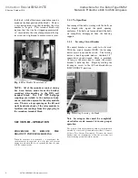
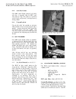
Fig. 9a
Handle in “OPEN”
Fig. 9b
Handle in “AUTO”
Fig. 9c
Handle in “CLOSE”
(Handle is shown with optional 90 degree handle ex tension.)
3.2.2.
Mechanical
Anti-Close
Interlock
(non-standard)
The Electrical Int erlock h as superceded this
device, see Addendum pg. 19. The Mechanical
Anti-Close Interlock is available on request only.
The CM52 is supplied with a mech anical anti-
close interlock, which interfaces with a welded
pad located on the inside edg e o f the en closure
door. This pad depresses an exposed rod that
will hold the breaker in a mechani cal trip free
state. It will also prevent electrical closure o f the
break er in the instance where a CM52 breaker is
being connected (lev ered-in) to en ergize bus and
the outside operating handle was left in the
AUTO position. The Anti-Close interlock
permits a close o f a b reaker in its connected
position only if the door has been closed and the
outside handle is placed either in the AUTO or
CLOSE positions. It is supplied with a defeat
mechanism, which permits an operator to open
the enclosure door while the break er remains
closed. This entire anti-close assembly is located
on the cassette and can be revers ed for either left
hand or right hand door hinging.
3.2.3
Installing
Network
Protecto r
to
Netwo rk Transformer
1. Remove front fuse cov er barrier cov er.
2. Remove fuse links or internal fuses.
3. Remove Interphase barriers by lifting
barrier up and tilting fo rward. The
barriers will lift directly out.
4. Mount
Network
Protector
to
trans former
fl ange
using
g asket
provided
by
the
trans form er
manu factu rer
and
th e
hardware*
provided with the Network Protector.
*Because o f the close p roximity between ph ases
A & B, and B & C to the throat mounting holes,
you may need to us e the fou r special Allen h ead
bolts with an Allen extender provided in the
hardware bag.
*On 800A – 2000A design units only
SECTION IV - CIRCUIT BREAKER
DESCRIPTION AND OPERATION
4.1 INTRODUCTION
CM52 circuit breakers are available in both draw
out and fix ed mounting con figu rations. A
majority of features are common to both
con figurations and will be discussed in this
section.
Controls and indicators for both draw out and
fix ed circuit break ers are fun ctionally grouped
on the front of the circuit breaker.
4.2
BASIC
CIRCUIT
BREAKER
ASSEMBLY
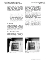
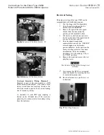
Fig. 10
CM52 w/ Breaker withdrawn
The CM52 circuit breakers use a rigid frame
housing construction of high temperatu re
engineered thermos et composite resins. This


