background image

62

Eaton 93PM UPS 480V Three-Wire – 100 kW Frame Installation and Operation Manual 164000227—Rev 07

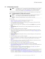
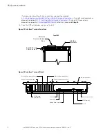
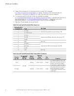
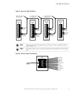
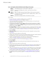
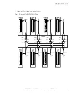
15. Connect the external parallel CAN wiring to the CAN terminals. See paragraph

3.2.4

UPS System Interface Wiring Preparation

,

Table 16

, and

Table 17

for wiring and termination

requirements, and

Figure 31

and

Figure 32

for wiring information and terminal assignments.

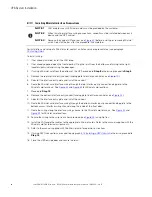
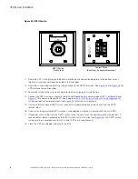
16. If wiring external parallel pull chain connections, proceed to paragraph

4.11.6

Installing External Parallel Pull Chain Control Wiring and Connections

; if wiring Minislot connections,

proceed to paragraph

4.11.7

Installing Minislot Interface Connections

if wiring REPO connections,

proceed to paragraph

4.12

Installing a REPO Switch

; otherwise, proceed to

Step 17

.

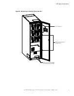
17. Close the UPS outside door and secure the latch.

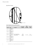
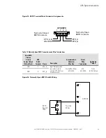
Table 16. External Parallel CAN and Pull Chain Connections

External Parallel

Terminal Block

Name

Description

1

Pull Chain

External parallel pull chain connections between UPSs.

2

Pull Chain Ground

3

CAN H In

External parallel CAN input connections from previous UPS.

4

CAN L In

5

Ground

6

Earth

Not Used

7

CAN H Out

External parallel CAN output connections to next UPS.

8

CAN L Out

9

Ground

10

Earth

Not Used

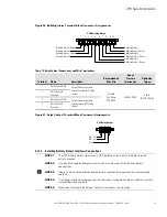
Table 17. External Parallel CAN and Pull Chain Terminal Block Terminations

Terminal

Function

Recommended

Minimum

Wire Size

Size of

Pressure

Termination

Tightening

Torque

Nm (lb in)

Type

Screw

Comments

CAN

#18 AWG

#26–#16

0.4 (3.5) - 0.8 (7.1)

Slotted

Use shielded twisted-pair wires with
drain wire for each input and return or
common. Strip wire insulation back
10 millimeters to wire terminal blocks.

Pull Chain

#26–#16

0.4 (3.5) - 0.8 (7.1)

Slotted

Use twisted-pair wires for each input
and return or common. Strip wire
insulation back 10 millimeters to wire
terminal blocks.

UPS System Installation

Summary of Contents for 93PM Series

Page 1: ...p n 164000227 Revision 07 480V Three Wire 100 kW Frame Installation and Operation Manual Eaton 93PM UPS ...

Page 2: ...roduced in any way without the express written approval of Eaton IMPORTANT SAFETY INSTRUCTIONS SAVE THESE INSTRUCTIONS This manual contains important instructions that you should follow during installation and maintenance of the UPS and batteries Please read all instructions before operating the equipment and save this manual for future reference CONSIGNES DE SÉCURITÉ IMPORTANTES CONSERVER CES INS...

Page 3: ...lid or unenforceable the remaining provisions of this Agreement will remain in full force 5 5 Waiver The waiver by either party of any default or breach of this Agreement will not constitute a waiver of any other or subsequent default or breach Failure to enforce or delay in enforcing any provision of this Agreement will not constitute a waiver of any rights under any provisions of this Agreement ...

Page 4: ......

Page 5: ...idecar Integrated Accessory Cabinet Tie Bypass 5 1 2 7 Integrated Accessory Cabinet Tie 5 1 2 8 Parallel System 5 1 2 9 Top Entry Wiring Sidecar 5 1 2 10 Monitoring and Communication 5 1 2 11 Additional Output Surge Protection 6 1 3 Battery System 6 1 4 Basic System Configurations 6 1 5 Using This Manual 6 1 6 Conventions Used in This Manual 7 1 7 Symbols Controls and Indicators 7 1 8 For More Inf...

Page 6: ...1 3 Installing Battery Shunt Trip Interface Connections 57 4 11 4 Generator Interface Connections 60 4 11 5 Installing External Parallel CAN Control Wiring and Connections 61 4 11 6 Installing External Parallel Pull Chain Control Wiring and Connections 64 4 11 7 Installing Minislot Interface Connections 66 4 12 Installing a REPO Switch 67 4 13 Initial Startup 70 4 14 Completing the Installation Ch...

Page 7: ...ency Power off Switch 105 7 4 Multiple External Parallel System Operation 107 7 4 1 Starting the Parallel System in Double Conversion Mode 107 7 4 2 Starting the Parallel System in Bypass Mode 107 7 4 3 Starting the Parallel System UPMs 108 7 4 4 Starting a Single UPM 108 7 4 5 Transfer from Double Conversion to Bypass Mode 108 7 4 6 Transfer from Bypass to Double Conversion Mode 109 7 4 7 Transfe...

Page 8: ... 118 9 9 C Co om mm mu un niic ca at tiio on n 1 11 19 9 9 1 Minislot Cards 119 9 2 Building Alarm Monitoring 120 9 3 General Purpose Relay Contact 120 9 4 PredictPulse Remote Monitoring and Management Service 120 9 4 1 PredictPulse Service Features 120 9 4 2 Installing PredictPulse 121 1 10 0 P Pr ro od du uc ct t S Sp pe ec ciif fiic ca at tiio on ns s 1 12 23 3 10 1 Model Numbers 123 10 2 Speci...

Page 9: ... 40 Figure 15 Removing the Sidecar Pallet Skids and Supports Eaton 93PM UPS 41 Figure 16 Removing the Sidecar Rear Shipping Bracket Eaton 93PM UPS 43 Figure 17 UPS Conduit and Wire Entry Locations 46 Figure 18 Sidecar Conduit and Wire Entry Locations 47 Figure 19 UPS Inter Cabinet Wiring Access Location 48 Figure 20 Power Terminal Locations 49 Figure 21 Power Terminal Detail 50 Figure 22 Interface...

Page 10: ...he LCD 88 Figure 50 Main Menu and Mimic Screen 89 Figure 51 Typical Meters Summary Screen 91 Figure 52 Typical Active Events Screen 92 Figure 53 Typical System Log Screen 92 Figure 54 Typical Settings User Screen 93 Figure 55 Typical Information Screen 93 Figure 56 Typical About Screen 94 Figure 57 Typical Settings Configuration 1 Screen 94 Figure 58 Typical Settings Configuration 2 Screen 95 Figu...

Page 11: ...put and Bypass Circuit Breaker Ratings 32 Table 10 Recommended Output Circuit Breaker Ratings 33 Table 11 Recommended DC Input Battery Disconnect Circuit Breaker Ratings 216 Cell 34 Table 12 Recommended DC Input Battery Disconnect Circuit Breaker Ratings 240 Cell 35 Table 13 Building Alarm Connections and Wire Terminations 54 Table 14 Relay Contact Connections and Wire Terminations 55 Table 15 Bat...

Page 12: ...xii Eaton 93PM UPS 480V Three Wire 100 kW Frame Installation and Operation Manual 164000227 Rev 07 List of Tables ...

Page 13: ...ed in a single free standing cabinet with safety shields behind the door for hazardous voltage protection Power wiring is installed through the bottom of the cabinet with an optional sidecar available for top entry wiring Figure 1 shows the Eaton 93PM 100 kW Frame UPS and Figure 2 shows the Eaton 93PM 100 kW Frame UPS with a left or right mounted sidecar NOTE Startup and operational checks must be...

Page 14: ... Frame Installation and Operation Manual 164000227 Rev 07 Figure 1 Eaton 93PM UPS 100 kW Frame Figure 2 Eaton 93PM UPS 100 kW Frame with Left or Right Mounted Sidecar UPS with Left Mounted Sidecar UPS with Right Mounted Sidecar Introduction ...

Page 15: ...information 1 1 1 1 5 5 I In nt te er rn na all R Re ed du un nd da an nc cy y To deliver greater reliability the Eaton 93PM UPS can be configured for internal redundancy When configured the UPS automatically becomes redundant if the load is at or below the capacity of the UPMs minus the capacity of one UPM Under normal conditions the UPMs in the UPS share the load equally If one or more UPMs beco...

Page 16: ...me can be provide by equipping the UPS system with up to four Integrated Battery Cabinets IBCs containing sealed lead acid maintenance free batteries The IBCs are housed in single free standing cabinets designed for line up and match installation but may be installed separate from the UPS cabinet An external battery disconnect switch or tie point must be used when three or four IBCs are located se...

Page 17: ...e recommended installation location for an adjacent IAC D is to the left of the UPS cabinet 1 1 2 2 8 8 P Pa ar ra alllle ell S Sy ys st te em m NOTE All UPSs in a parallel system must have the same battery configuration Each UPS requires a separate battery cabinet A parallel UPS system with up to eight UPSs can be installed to provide a parallel capacity and or redundant system This load sharing ...

Page 18: ...ffers a variety of SPD solutions including the Eaton SPD Series with various kA ratings options 1 1 3 3 B Ba at tt te er ry y S Sy ys st te em m Although not provided with the UPS a battery system is required to provide emergency short term backup power to safeguard operation during brownouts blackouts and other power interruptions The battery system should be equipped with lead acid batteries An ...

Page 19: ...dous waste center This symbol indicates that you should not discard waste electrical or electronic equipment WEEE in the trash For proper disposal contact your local recycling reuse or hazardous waste center Eaton Powerware and BladeUPS are registered trademarks of Eaton Corporation or its subsidiaries and affiliates CAUTION REFER TO OPERATOR S MANUAL Refer to your operator s manual for additional...

Page 20: ...ures and optional accessories procedures for using the bypass functions and information about maintenance Refer to the Eaton 93PM Integrated Accessory Cabinet Tie 50 kW and 100 kW IAC T Installation and Operation Manual for the following additional information Installation instructions including site preparation planning for installation wiring and safety information and detailed illustrations of ...

Page 21: ...ual does not answer Please call the Customer Reliability Center at United States 1 800 843 9433 Canada 1 800 461 9166 ext 260 All other countries Call your local service representative Please use the following e mail address for manual comments suggestions or to report an error in this manual E ESSDocumentation eaton com 1 1 1 10 0 E Eq qu uiip pm me en nt t R Re eg giis st tr ra at tiio on n Plea...

Page 22: ...10 Eaton 93PM UPS 480V Three Wire 100 kW Frame Installation and Operation Manual 164000227 Rev 07 Introduction ...

Page 23: ... temperature must not exceed 40 C 104 F Do not operate near water or excessive humidity 95 maximum The system is not intended for outdoor use As a result of the connected loads high leakage current is possible Connection to earth ground is required for safety and proper product operation Do not check UPS operation by any action that includes removal of the earth ground connection with loads attach...

Page 24: ...Do not install or operate the UPS system close to gas or electric heat sources Lead acid batteries can present a risk of fire because they generate hydrogen gas Do not smoke when near batteries Do not cause flame or spark in battery area Discharge static electricity from body before touching batteries by first touching a grounded metal surface The operating environment should be maintained within ...

Page 25: ... for installing the system 3 3 2 2 P Pr re ep pa ar riin ng g t th he e S Siit te e For the UPS system to operate at peak efficiency the installation site should meet the environmental parameters outlined in this manual The operating environment must meet the weight clearance and environmental requirements specified 3 3 2 2 1 1 E En nv viir ro on nm me en nt ta all a an nd d I In ns st ta alllla a...

Page 26: ...hen ignored either one of these aspects can create an undesirable microclimate at the UPS location If the environment created by this microclimate exceeds the UPS operating specification the UPS reliability over time will be reduced These same environmental extremes will also create reliability concerns for any servers that are exposed to them Failure to follow guidelines may void your warranty Th...

Page 27: ...3PM 100 2 Eaton 93PM 100 3 N 1 70 kW 480 480 8 36 2108 Eaton 93PM 100 2 Eaton 93PM 100 3 N 1 80 kW 480 480 9 12 2300 Eaton 93PM 100 2 Eaton 93PM 100 3 N 1 90 kW 480 480 10 26 2588 Eaton 93PM 100 2 Eaton 93PM 100 3 N 1 100 kW 480 480 11 40 2875 The UPS equipment operating environment must meet the weight requirements shown in Table 2 and the size requirements shown in Figure 3 through Figure 10 Dim...

Page 28: ...12 Top Entry Wiring Sidecar no breakers 74 162 Four breaker SIAC B 106 233 The UPS cabinet uses forced air cooling to regulate internal component temperature Air inlets are in the front of the cabinet and outlets are on top or in the back of the cabinet Allow clearance in front of and on top or in back of the cabinet for proper air circulation The clearances required around the UPS cabinet are sho...

Page 29: ...ree Wire 100 kW Frame Installation and Operation Manual 164000227 Rev 07 17 Figure 3 UPS Cabinet Dimensions Front and Right Side Views Front Right Side Dimensions are in millimeters Inches UPS Installation Plan and Unpacking ...

Page 30: ...Frame Installation and Operation Manual 164000227 Rev 07 Figure 4 UPS Cabinet Dimensions Top and Bottom Views Dimensions are in millimeters inches NOTE Top exhaust configuration shown Front Bottom Top Front UPS Installation Plan and Unpacking ...

Page 31: ...ng Dimensions Back Views Dimensions are in millimeters inches UPS with Left Mounted SIAC B Bypass Sidecar Note All examples shown with top exhaust option UPS with Left Mounted Top Entry Wiring Sidecar UPS NOTE The UPS Front Floor Mounting Bracket s mounting dimensions are identical to the Rear Floor Mounting Bracket dimensions UPS Installation Plan and Unpacking ...

Page 32: ...anual 164000227 Rev 07 Figure 6 UPS Cabinet with Left or Right Mounted Sidecar Dimensions Front Views Front UPS With Left Mounted Sidecar Front UPS With Right Mounted Sidecar Dimensions are in millimeterse Inches 1880 74 0 762 762 30 0 30 0 UPS Installation Plan and Unpacking ...

Page 33: ...00227 Rev 07 21 Figure 7 UPS Cabinet with Left or Right Mounted Sidecar Dimensions Top and Bottom Views Dimensions are in millimeters Inches Top Top Bottom Bottom UPS With Left Mounted Sidecar UPS With Right Mounted Sidecar Front Front Front Front UPS Installation Plan and Unpacking ...

Page 34: ...mensions are in millimeters Inches Weight and Center of Gravity letters A B and C map to Figure 8 A mm in B mm in C mm in Weight kg lb Eaton 93PM 100 1 UPS 842 33 1 537 21 1 276 10 8 337 743 Eaton 93PM 100 2 UPS 921 36 3 537 21 1 276 10 8 394 869 Eaton 93PM 100 3 UPS 1022 40 2 537 21 1 276 10 8 470 1037 UPS Installation Plan and Unpacking ...

Page 35: ...with Top Entry Wiring Sidecar no breakers 844 33 2 542 21 3 409 16 1 406 894 Eaton 93PM 100 2 UPS with Top Entry Wiring Sidecar no breakers 911 35 8 541 21 3 419 16 5 469 1034 Eaton 93PM 100 3 UPS with Top Entry Wiring Sidecar no breakers 1001 39 4 541 21 3 427 16 8 539 1188 Eaton 93PM 100 1 UPS with four breaker SIAC B 855 33 7 568 22 4 390 15 4 433 954 Eaton 93PM 100 2 UPS with four breaker SIAC...

Page 36: ... 4 50 0 87 0 22 88 9 3 50 1 57 0 40 95 3 3 57 Dimensions are in millimeters Inches 1 2 Knockout Pattern Typical 5 sides Square Needed to remove key Front View 3 3 2 2 2 2 U UP PS S S Sy ys st te em m P Po ow we er r W Wiir riin ng g P Pr re ep pa ar ra at tiio on n NOTE Refer to the Eaton 93PM Sidecar Integrated Accessory Cabinet Tie and Tie Bypass 50 kW and 100 kW SIAC T and 50 kW and 100 kW SIAC...

Page 37: ... TT 3 wire High Resistance Ground IT Supported dual source dual feed power sources 3 wire grounded Wye TN TT CAUTION SINGLE HIGH IMPEDANCE GROUND SOURCE In North American installations the neutral conductor from the high impedance ground source of supply CANNOT be used Phase rotation must be clockwise starting with phase A rotation A B C If installing an external maintenance bypass all feeds to th...

Page 38: ...rnal Parallel Wire Length NOTE Required parallel system wiring length must be equal to ensure approximately equal current sharing when in Bypass mode For proper operation the following must be true 1A 2A 3A 4A 1B 2B 3B 4B NOTE Any difference in wire length will result in decreased capacity of the UPS system while on bypass For example a 10 difference between the longest and shortest wire lengths w...

Page 39: ... 3 1 Minimum Conductor Size Ground Number AWG or kcmil each 10 1 10 1 8 1 8 1 DC Input from External Battery Line Up and Match Eaton 93PM IBC 1 Positive 1 Negative 1 Ground C Total Amps 216 cell Total Amps 240 cell 50 45 74 67 99 89 124 111 Minimum Conductor Size Phase Pos and Neg Number per Pole AWG or kcmil each 2 0 1 See Note 2 0 1 See Note 2 0 1 See Note 2 0 1 See Note Minimum Conductor Size G...

Page 40: ...nductor Size Phase A B and C Number per Phase AWG or kcmil each 1 1 1 0 1 2 0 1 2 0 1 3 0 1 Minimum Conductor Size Ground Number AWG or kcmil each 6 1 6 1 6 1 6 1 6 1 AC Input to UPS Bypass Three Wire Dual Feed Full Load Current 3 Phases 1 Ground B Amps 94 108 120 133 146 Minimum Conductor Size Phase A B and C Number per Phase AWG or kcmil each 1 1 1 0 1 2 0 1 2 0 1 3 0 1 Minimum Conductor Size Gr...

Page 41: ...rminations UL and CSA rated See Table 6 for external power cable terminations Figure 20 and Figure 21 show the location of the UPS power cable terminals Table 6 UPS External Power Cable Terminations Terminal Function Terminal Function Number and Size of Pressure Termination AWG or kcmil Tightening Torque Nm lb in Screw Size and Type AC Input to UPS Rectifier E1 Phase A 2 6 250 kcmil 22 6 200 1 4 H...

Page 42: ...ted for use with copper wire only For external wiring use only 75 C copper wire Table 7 Power Cable Conduit Recommendations Eaton 93PM 100 1 and Eaton 93PM 100 2 N 1 UPS Model UPS Rating Voltage Terminal Number of Wires in Conduit Minimum Conduit Trade Size Number of Conduits Eaton 93PM 100 1 Eaton 93PM 100 2 N 1 20 kW 480 Vac AC Input to UPS Rectifier and Bypass A B C Ground 4 3 4 1 AC Output Thr...

Page 43: ... Eaton 93PM 100 2 and Eaton 93PM 100 3 N 1 UPS Model UPS Rating Voltage Terminal Number of Wires in Conduit Minimum Conduit Trade Size Number of Conduits Eaton 93PM 100 2 Eaton 93PM 100 3 N 1 60 kW 480 Vac AC Input to UPS Rectifier and Bypass A B C Ground 4 1 1 2 1 AC Output Three Wire A B C Ground 4 1 1 4 1 DC Battery Positive Negative Ground 5 2 1 2 1 Eaton 93PM 100 2 Eaton 93PM 100 3 N 1 70 kW ...

Page 44: ...e Ground 5 2 1 2 1 NOTE Wires per conduit include ground wire External overcurrent protection and disconnect are not provided by this product but are required by codes See Table 4 or Table 5 for wiring recommendations If an output lockable disconnect is required it is to be supplied by the customer Table 9 lists the recommended rating for input and bypass circuit breakers Table 9 Recommended Input...

Page 45: ...f the UPS is limited only by the full load per phase current values for AC output to critical load shown in Table 4 or Table 5 The recommended line to line load unbalance is 50 or less Bypass and output overcurrent protection and bypass and output disconnect switches are to be supplied by the customer Table 10 lists the recommended rating for output circuit breakers Table 10 Recommended Output Cir...

Page 46: ...is to be supplied by the customer Table 11 and Table 12 list the recommended ratings for circuit breakers satisfying the criteria for each battery voltage Recommended disconnect size is based on a maximum full load discharge time less than 3 hours For longer discharge times a larger disconnect may be required Table 11 Recommended DC Input Battery Disconnect Circuit Breaker Ratings 216 Cell Output ...

Page 47: ...r Integrated Accessory Cabinet Tie and Tie Bypass 50 kW and 100 kW SIAC T and 50 kW and 100 kW SIAC TB Installation and Operation Manual listed in paragraph 1 8 For More Information for SIAC T and SIAC TB interface wiring preparation and requirements Control wiring for features and options should be connected at the customer interface terminal blocks located inside the UPS WARNING Do not directly ...

Page 48: ...y disconnect device Program the battery detect building alarm to read battery open and for normally open contacts A supplemental 48 Vdc shunt trip signal for the battery disconnect device is provided but is not required for normal operation Battery detect and 48 Vdc shunt trip wiring should be a minimum of 18 AWG The REPO feature opens all switchgear in the UPS cabinet and isolates power from your...

Page 49: ...or the following step verify that the forklift or pallet jack is rated to handle the weight of the cabinet see Table 2 for cabinet weight 2 Use a forklift or pallet jack to move the packaged cabinet to the installation site or as close as possible before unpacking If possible move the cabinet using the pallet Insert the forklift or pallet jack forks between the supports on the bottom of the pallet...

Page 50: ...nd Operation Manual 164000227 Rev 07 Figure 12 UPS Cabinet as Shipped on Pallet Figure 13 UPS Cabinet with Left Mounted or Right Mounted Sidecar as Shipped on Pallet UPS with Left Mounted Sidecar UPS with Right Mounted Sidecar UPS Installation Plan and Unpacking ...

Page 51: ...inet more than 10 from vertical Lift the cabinets only with a forklift or damage may occur Ensure the forklift is rated to handle the weight of the cabinet Failure to follow these instructions may result in severe injury or death The UPS cabinet is bolted to a pallet consisting of four metal angle supports secured to two wood supports To remove the pallet 1 If not already accomplished use a forkli...

Page 52: ...loading instructions are not closely followed the cabinet may tip and cause serious injury or death 4 Loosen but do not remove the skid mounting bolts holding the pallet skids to the front and rear supports and to the left and right side supports 5 If a sidecar is attached to the UPS loosen but do not remove the sidecar skid mounting bolts holding the sidecar pallet skids to the sidecar front and ...

Page 53: ...ng the jacking bolts Recycle the pallet skids and hardware in a responsible manner CAUTION CABINET MAY FALL Do not loosen the hardware attaching the front supports to the cabinet base The cabinet must be lowered by the jacking bolts before the supports can be removed If unpacking and unloading instructions are not closely followed the cabinet may tip and cause serious injury or death 10 Carefully ...

Page 54: ...he UPS locate the top splice bracket shipped with the IBC otherwise go to Step 25 23 Remove the screws along each adjacent cabinet top panel securing the top panels Retain the hardware for later use 24 Install the top splice bracket between the adjacent cabinet and secure the tie strap with retained hardware NOTE Either front and back floor mounting brackets or left and right side floor mounting b...

Page 55: ...2V and 480V Installation Manual listed in paragraph 1 8 For More Information for installation instructions After the IBC is installed proceed to paragraph 4 4 Sidecar Integrated Accessory Cabinet Bypass Wiring Installation if a Sidecar Integrated Accessory Cabinet Bypass SIAC B is attached to the UPS or to paragraph 4 5 Sidecar Integrated Accessory Cabinet Tie Wiring Installation if a Sidecar Inte...

Page 56: ...d Accessory Cabinet Distribution IAC D otherwise proceed to paragraph 4 9 External AC Power Wiring Installation to complete the wiring of the UPS 4 4 6 6 S Siid de ec ca ar r I In nt te eg gr ra at te ed d A Ac cc ce es ss so or ry y C Ca ab biin ne et t T Tiie e B By yp pa as ss s W Wiir riin ng g I In ns st ta alllla at tiio on n If an SIAC TB is attached to the UPS refer to the Eaton 93PM Sidec...

Page 57: ...emove the panel to gain access to the interior of the sidecar and the UPS inter cabinet wiring access pass through Retain the hardware for later use 9 Top Entry Wiring Remove the top conduit plate see Figure 18 from the top of the sidecar Identify all conduit requirements and mark their location Drill and punch all conduit holes in the top conduit plate prior to mounting on the sidecar Install the...

Page 58: ...he tie cabinet 16 Proceed to Step 17 17 Connect phase A B and C power wiring from output terminals to the critical load See paragraph 3 2 2 UPS System Power Wiring Preparation for wiring and termination requirements 18 Proceed to paragraph 4 10 Battery Power Wiring Figure 17 UPS Conduit and Wire Entry Locations Top Entry Conduit Landings for Customer Interface Wiring NOTE Remove panels to drill or...

Page 59: ...y Conduit Landings for Customer Interface Wiring Top Entry Conduit Landing for AC Input and Output and DC Input Bottom Entry Conduit Landing for AC Input and Output and DC Input Top View Rear Exhaust Option Front Bottom View Bottom Entry Conduit Landings for Customer Interface Wiring NOTE Remove panels to drill or punch conduit holes UPS System Installation ...

Page 60: ...7 Rev 07 Figure 19 UPS Inter Cabinet Wiring Access Location Inter cabinet wiring access to route interface wiring between cabinets Inter cabinet wiring access knockouts Remove knockouts as required to route power wiring between cabinets Left Side View Right Side View UPS System Installation ...

Page 61: ...kW Frame Installation and Operation Manual 164000227 Rev 07 49 Figure 20 Power Terminal Locations AC Input to UPS Bypass A B C AC Input to UPS Rectifier A B C DC Input from Battery AC Output to Critical Load A B C UPS System Installation ...

Page 62: ...grated Battery Cabinet Installation Manual Large and Large High Rate the Eaton 93PM Integrated Battery Cabinet Installation Manual Small or the Eaton 93PM Integrated Battery Cabinet Small Welded IBC SW 432V and 480V Installation Manual listed in paragraph 1 8 For More Information See Figure 17 Figure 18 and Figure 19 for wiring access information and Figure 20 for terminal locations 2 Ground the s...

Page 63: ...y output interface wiring through the top interface entry conduit landing plates to the UPS building alarm and relay output terminals See Figure 22 and Figure 23 for UPS interface terminal locations 7 Proceed to Step 13 8 Bottom Entry Wiring Remove the bottom interface entry conduit landing plates to drill or punch holes see Figure 18 9 Reinstall the interface entry plates and install the conduit ...

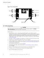
Page 64: ...s proceed to paragraph 4 12 Installing a REPO Switch otherwise proceed to Step 16 16 Close the UPS outside door and secure the latch Figure 22 Interface Terminal Locations Pull Chain and CANTerminals Interface Terminals Minislot Communication Bays Top of UPS Figure 23 Interface Terminal Detail Minislot Communication Bay 2 Minislot Communication Bay 1 Minislot Communication Bay 3 Minislot Communica...

Page 65: ... Installation and Operation Manual 164000227 Rev 07 53 Figure 24 Bottom Access Interface Wiring Location Wire Tie Anchors Bottom Access Interface Wiring Channel Bottom Entry Conduit Landings for Customer Interface Wiring UPS System Installation ...

Page 66: ...ed Wire Size Size of Pressure Termination Tightening Torque 10 Building Alarm 1 Input Programmable UPS alarm activated by a remote dry contact closure Twisted Pair Wires 18 AWG 14 30 AWG 2 lb in 0 22 0 25 Nm 9 Building Alarm 1 Return 8 Building Alarm 2 7 Building Alarm 2 Return 6 Building Alarm 3 5 Building Alarm 3 Return 4 Building Alarm 4 3 Building Alarm 4 Return 2 Building Alarm 5 1 Building A...

Page 67: ...m 3 Relay Contact Common 2 Relay Contact NO Output General purpose normally open NO relay contact 3 Relay Contact Common Figure 27 Relay Contact Terminal Block Connector Assignments UPS Relay Output 1 2 3 NO_Out NC_Out Com 4 4 1 11 1 2 2 I In ns st ta alllliin ng g B Ba at tt te er ry y D De et te ec ct t I In nt te er rf fa ac ce e C Co on nn ne ec ct tiio on ns s NOTE 1 The UPS battery detect si...

Page 68: ...iring from the battery cabinet through the bottom interface entry conduit landing plate to the bottom access interface wiring channel along the inside of the front door see Figure 24 9 Route the wiring along the interface wiring channel to the UPS building alarm terminals See Figure 22 and Figure 23 for UPS interface terminal locations 10 Secure the wiring to the wire tie anchors provided see Figu...

Page 69: ...d in paragraph 1 8 For More Information for battery cabinet wiring access information and instructions 6 Pass through Wiring Route the battery shunt trip wiring from the battery cabinet through the bottom UPS inter cabinet wiring access pass through and static switch shelf bushing to the UPS battery shunt trip terminals See Figure 19 for UPS wiring access information and Figure 28 and Figure 29 fo...

Page 70: ...stall all safety shield panels previously removed and secure with the retained hardware 14 If removed reinstall the sidecar front panel and secure with the retained hardware 15 Close the UPS outside door and secure the latch Figure 28 Battery Shunt Trip Location Shunt Trip Terminals UPS System Installation ...

Page 71: ...e 15 Battery Shunt Trip Connections and Wire Terminations Terminal Name Description Recommended Wire Size Size of Pressure Termination Tightening Torque 1 48 Vdc Battery Shunt Trip Output Contacts used to open battery breaker or disconnect Twisted Pair Wires 18 AWG 14 30 AWG 2 lb in 0 22 0 25 Nm 2 48 Vdc Battery Shunt Trip 3 Not Used 4 Not Used UPS System Installation ...

Page 72: ...ire plugs To Install wiring 1 Verify the UPS system is turned off and all power sources are removed See Chapter 7 UPS Operating Instructions for shutdown instructions 2 If not already opened open the front door by lifting the latch from the bottom and turning to the right counterclockwise and swing the door open 3 If wiring the interface terminals from the bottom of the UPS proceed to Step 8 other...

Page 73: ...the bottom and turning to the right counterclockwise and swing the door open 3 If wiring the external parallel CAN connections using the inter cabinet wiring access pass through line up and match configurations proceed to Step 4 if wiring the external parallel CAN connections using bottom entry access proceed to Step 6 if wiring the external parallel CAN connections using top entry access proceed ...

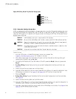
Page 74: ...e 16 External Parallel CAN and Pull Chain Connections External Parallel Terminal Block Name Description 1 Pull Chain External parallel pull chain connections between UPSs 2 Pull Chain Ground 3 CAN H In External parallel CAN input connections from previous UPS 4 CAN L In 5 Ground 6 Earth Not Used 7 CAN H Out External parallel CAN output connections to next UPS 8 CAN L Out 9 Ground 10 Earth Not Used...

Page 75: ...r Termination 121 Ohm Resistor Parallel CAN In Parallel CAN In Parallel CAN In UPS 1 UPS 2 UPS 3 If Installed UPS 4 If Installed 1 2 3 4 5 6 7 8 9 10 1 2 3 4 5 6 7 8 9 10 1 2 3 4 5 6 7 8 9 10 1 2 3 4 5 6 7 8 9 10 NOTE External parallel CAN connections between UPS cabinets require shielded twisted pair wire with drain wire NOTE Terminations are 121 ohm 1 resistors installed in the terminal block in...

Page 76: ...rnal parallel terminals See Figure 19 for UPS wiring access information and Figure 22 and Figure 23 for UPS interface terminal locations 5 Proceed to Step 15 6 Bottom Entry Wiring Remove the bottom interface entry conduit landing plate to drill or punch holes see Figure 24 7 Reinstall the interface entry plate and install the conduit 8 Route the external parallel pull chain control wiring through ...

Page 77: ...ed External Parallel TB Pull Chain 1 2 3 4 5 6 7 8 9 10 UPS 3 If Installed Building Alarm TB AUX 1 AUX 2 Tie Cabinet MOB 1 MOB 2 MOB 3 MOB 4 COM COM COM COM COM COM COM COM Twisted Pair Twisted Pair Twisted Pair Twisted Pair NC NO NC NO NC NO NC NO NC NO NC NO NC NO NC NO AUX 1 AUX 2 AUX 1 AUX 2 AUX 1 AUX 2 1 2 3 4 5 6 7 8 9 10 UPS 1 If Installed Building Alarm TB 1 2 3 4 5 6 7 8 9 10 UPS 2 If Ins...

Page 78: ...unch holes see Figure 17 5 Reinstall the interface entry plate and install the conduit 6 Route the Minislot card interface wiring through the top interface entry conduit landing plate to the Minislot card terminals See Figure 22 and Figure 23 for Minislot card locations 7 Proceed to Step 13 8 Remove the bottom interface entry conduit landing plate to drill or punch holes see Figure 24 9 Reinstall ...

Page 79: ...ring must be in accordance with NEC Article 725 Class 2 requirements NOTE 6 Disconnect terminal block plugs from terminal blocks to wire plugs To Install a REPO switch 1 Verify the UPS system is turned off and all power sources are removed See Chapter 7 UPS Operating Instructions for shutdown instructions 2 Securely mount the REPO switch Recommended locations include operator s consoles or near ex...

Page 80: ...iring as shown in Table 18 and Figure 36 for a normally open REPO or Table 19 and Figure 37 for a normally closed REPO See paragraph 3 2 4 UPS System Interface Wiring Preparation for wiring and termination requirements and Figure 35 for terminal assignments 15 If using a normally closed REPO switch connect a jumper wire between pins 3 and 4 on the REPO terminal block 16 If you are installing multi...

Page 81: ... REPO Connections and Wire Terminations From REPO Station Switch Contact Block Either Block UPS REPO Terminal Name Description Recommended Minimum Wire Size Size of Wire Termination Tightening Torque 3 NO 3 EPO_A Input Normally open dry contact used to activate UPS EPO from a remote switch Twisted Pair Wires 18 AWG 16 30 AWG 2 lb in 0 22 0 25 Nm 4 NO 4 EPO_B Figure 36 Normally Open REPO Switch Wir...

Page 82: ...n 0 22 0 25 Nm 4 NO 2 GND ISO Figure 37 Normally Closed REPO Switch Wiring 3 1 2 4 1 2 REPO Switch NC Twisted Wires REPO TB 4 4 1 13 3 I In niit tiia all S St ta ar rt tu up p Startup and operational checks for parallel systems or installations with accessory cabinets must be performed by an authorized Eaton Customer Service Engineer or the warranty terms specified on the product s resources page ...

Page 83: ...wer cables are properly sized and terminated o Battery cables are terminated on E4 and E5 o Battery shunt trip signal wiring is connected from the UPS to the battery disconnect o Battery detect signal wiring is connected from the UPS to the battery disconnect o A ground conductor is properly installed o Building alarms and alarm relays are wired appropriately Optional o LAN drops are installed Opt...

Page 84: ..._____________________________ _________________________________________________________________________ _________________________________________________________________________ _________________________________________________________________________ _________________________________________________________________________ _________________________________________________________________________ ...

Page 85: ... a backup battery supply to maintain power to the critical load for a specified period of time or until the utility power returns For extended power outages the UPS allows you to either transfer to an alternative power system such as a generator or shut down your critical load in an orderly manner The emergency bypass consists of a continuous static switch and bypass switchgear The bypass switchge...

Page 86: ...ectly to the critical load through the internal bypass and transfers automatically to Normal mode double conversion on demand if an abnormal condition is detected The battery charger also provides charging current for the battery if needed In Normal double conversion mode the critical load is supplied by the inverter which derives its power from rectified utility AC power In this mode the battery ...

Page 87: ...ement of power converters Typical transition time to double conversion is less than two milliseconds which is practically seamless If the UPS detects a fault condition while operating in ESS it is also able to detect and determine whether the fault is caused by the load or if it is upstream from the UPS A fault at the bypass source results in an immediate switch over to the inverter A fault in the...

Page 88: ...d without the use of a transformer The inverter derives regulated DC from the rectifier and uses IGBT devices and pulse width modulation PWM to produce a regulated and filtered AC output The AC output of the inverter is delivered to the system output through the inverter switchgear If the utility AC power is interrupted or is out of specification the UPS automatically switches to Battery mode to s...

Page 89: ...eration The internal bypass is comprised of a solid state silicon controlled rectifier SCR continuous duty static switch and bypass switchgear The static switch is used instantaneously anytime the inverter is unable to support the applied load The continuous static switch is wired in series with the bypass switchgear and together they are wired in parallel with the rectifier and inverter The stati...

Page 90: ...ents to the utility source If the input power fails to return or is not within the acceptance windows required for normal operation the battery continues discharging until a DC voltage level is reached where the inverter output can no longer support the connected loads When this event occurs the UPS issues another set of audible and visual alarms indicating SHUTDOWN IMMINENT Unless the rectifier h...

Page 91: ...ss Oneline Drawing UPS Model System Type See Figure 43 93PM UPS Reverse transfer UPS with up to 3 UPMs with external battery See Figure 44 93PM UPS with a 2 Breaker SIAC B Reverse transfer UPS with up to 3 UPMs with two breaker bypass and external battery See Figure 45 93PM UPS with a 3 Breaker SIAC B Reverse transfer UPS with up to 3 UPMs with three breaker bypass and external battery See Figure ...

Page 92: ...E8 Optional Single Feed Jumper Fuse Fuse Fuse Fuse Rectifier Switchgear Rectifier Inverter Inverter Switchgear Battery Converter Battery Switchgear Fuse Fuse Fuse Rectifier Switchgear Rectifier Inverter Inverter Switchgear Battery Converter Battery Switchgear UPM 2 Fuse Fuse Fuse Rectifier Switchgear Rectifier Inverter Inverter Switchgear Battery Converter Battery Switchgear UPM 3 E4 E5 Battery Br...

Page 93: ... Cabinet Not supplied with the UPS E6 E7 E8 Optional Single Feed Jumper Fuse Fuse Fuse Fuse Rectifier Switchgear Rectifier Inverter Inverter Switchgear Battery Converter Battery Switchgear UPM 1 Fuse Fuse Fuse Rectifier Switchgear Rectifier Inverter Inverter Switchgear Battery Converter UPM 2 Fuse Fuse Fuse Rectifier Switchgear Rectifier Inverter Inverter Switchgear Battery Converter UPM 3 E4 E5 B...

Page 94: ...gle Feed Jumper Fuse Fuse Fuse Fuse Rectifier Switchgear Rectifier Inverter Inverter Switchgear Battery Converter Battery Switchgear UPM 1 Fuse Fuse Rectifier Switchgear Rectifier Inverter Inverter Switchgear Battery Converter Battery Switchgear UPM 2 Fuse Fuse Rectifier Switchgear Rectifier Inverter Inverter Switchgear Battery Converter Battery Switchgear UPM 3 E4 E5 Battery Breaker Bypass Switch...

Page 95: ... E8 E6 E7 E8 Fuse Fuse Fuse Fuse Rectifier Switchgear Rectifier Inverter Inverter Switchgear Battery Converter Battery Switchgear UPM 1 Fuse Fuse Fuse Rectifier Switchgear Rectifier Inverter Inverter Switchgear Battery Converter Battery Switchgear UPM 2 Fuse Fuse Fuse Rectifier Switchgear Rectifier Inverter Inverter Switchgear Battery Converter Battery Switchgear UPM 3 E4 E5 Battery Breaker Bypass...

Page 96: ...84 Eaton 93PM UPS 480V Three Wire 100 kW Frame Installation and Operation Manual 164000227 Rev 07 UPS Oneline Schematics ...

Page 97: ...e of UPS operation before attempting to operate any of the controls 7 7 1 1 U UP PS S C Co on nt tr ro olls s a an nd d I In nd diic ca at to or rs s The controls and indicators identified and described in this section are used to set up control and monitor UPS operation Figure 47 shows the control panel location on the front door of the UPS For a description of the UPS control panel functions and...

Page 98: ...ibe using the UPS control panel to monitor the UPS See paragraph 7 3 Single UPS Operation for use of the operational controls When the unit powers up the screen displays the as shown in Figure 48 7 7 2 2 1 1 S St ta at tu us s I In nd diic ca at to or rs s The four symbols on the bottom of the control panel are status indicators These colored light emitting diode LED lamps work with the alarm horn...

Page 99: ...u screen to display the active events screen This screen shows any currently active alarms notices or commands For more information on using the events screen see paragraph 7 2 6 Display Menu Operation System Event Horns The system event horn beeps to alert an operator that an event needing attention is taking place The horn cycles at a half second rate To silence the horn touch any control panel ...

Page 100: ...s tab buttons To select a screen function touch the tab name D Information Area contains status data operational controls acknowledgments action confirmations and screen prompts You can use the LCD touch screen to Look at a log of UPS events alarms notices and commands see paragraph 7 2 6 Display Menu Operation Monitor UPS operation see paragraph 7 2 6 Display Menu Operation Set UPS parameters see...

Page 101: ...us screen controlled variables for the system operation Settings include date and time for the time stamp display language the unit name meter subscripts password and view the firmware version numbers Used only by service personnel NOTE Screens shown are representative examples of system operation The screen data will vary based on system activity at the time of observation 7 7 2 2 5 5 M Miim miic...

Page 102: ... menu navigation bar to display an overview of UPS operation including information on load efficiency and consumption If there is an error an error indicator is displayed next to the affected part Active events log can be opened by tapping the error indicator UPS Module Map Tap the UPS MODULE MAP tab on the secondary menu navigation bar to display the status of each UPM System Overview Tap the SYS...

Page 103: ...he secondary menu navigation bar to display the screen Tap the function to be changed Make and save the changes Follow screen prompts to accept or abort changes For additional functions tap the 2 button See Figure 57 and Figure 58 for configuration screens Statistics Statistics Summary Tap the STATISTICS tab on the main menu navigation bar to display a summary of UPS statistics see Figure 59 Stati...

Page 104: ...92 Eaton 93PM UPS 480V Three Wire 100 kW Frame Installation and Operation Manual 164000227 Rev 07 Figure 52 Typical Active Events Screen Figure 53 Typical System Log Screen UPS Operating Instructions ...

Page 105: ...Eaton 93PM UPS 480V Three Wire 100 kW Frame Installation and Operation Manual 164000227 Rev 07 93 Figure 54 Typical Settings User Screen Figure 55 Typical Information Screen UPS Operating Instructions ...

Page 106: ... Eaton 93PM UPS 480V Three Wire 100 kW Frame Installation and Operation Manual 164000227 Rev 07 Figure 56 Typical About Screen Figure 57 Typical Settings Configuration 1 Screen UPS Operating Instructions ...

Page 107: ...en 7 7 2 2 7 7 S Siig gn n I In n The Controls and Setting screens are restricted The user must sign in using a password to gain access CAUTION To prevent inadvertent or unauthorized power disruption to the critical load or auxiliary lighting system change the Level 1 and Level 2 default passwords when system commissioning startup is performed To Sign in UPS Operating Instructions ...

Page 108: ...is displayed see Figure 60 2 Tap the password entry area on the screen 3 Enter the password using the keypad displayed and tap the return key see Figure 61 Level 1 default password is 1111 Settings Level 2 default password is 0101 4 Sign in is complete Tap continue to return to previous screen Figure 60 Sign In Password Screen Figure 61 Sign In Keypad UPS Operating Instructions ...

Page 109: ...tem Controls see paragraph 7 3 Single UPS Operation or 7 4 Multiple External Parallel System Operation Figure 62 through Figure 66 show the major control screens Table 23 Controls Menu Operation Function Subfunction Operation System Controls The CONTROLS tab on the main menu navigation bar displays the System Controls screen System Status GO ONLINE starts the UPS in Double Conversion mode or trans...

Page 110: ...98 Eaton 93PM UPS 480V Three Wire 100 kW Frame Installation and Operation Manual 164000227 Rev 07 Figure 62 Typical System Control Screen Figure 63 Typical UPS Control Screen UPS Operating Instructions ...

Page 111: ...Eaton 93PM UPS 480V Three Wire 100 kW Frame Installation and Operation Manual 164000227 Rev 07 99 Figure 64 Typical UPM Select Screen Figure 65 Typical UPM Control Screen UPS Operating Instructions ...

Page 112: ... provide power to the load 7 7 3 3 1 1 S St ta ar rt tiin ng g t th he e U UP PS S iin n D Do ou ub blle e C Co on nv ve er rs siio on n M Mo od de e To start the UPS system 1 Close the UPS input feeder circuit breaker 2 If dual feed close the UPS bypass feeder circuit breaker 3 If IBCs are installed close the battery breakers 4 Observe the UPS control panel display becoming active indicating logi...

Page 113: ...he UPS input feeder circuit breaker 2 If dual feed close the UPS Bypass input feeder circuit breaker 3 Observe the UPS control panel becoming active indicating logic power 4 Verify no alarms are active 5 Tap the CONTROLS tab on the main menu navigation bar The System Control screen is displayed 6 Tap the MODULES CONTROLS tab on the secondary Control menu navigation bar The UPM Select screen is dis...

Page 114: ...trol screen is displayed 2 Tap the GO TO BYPASS button The UPS transfers to Bypass mode and the critical load is immediately supplied by the bypass source If the bypass source is not available the power module remains on and an alarm sounds The BYPASS status indicator is illuminated The power module remains on WARNING Power is present inside the UPS cabinet 7 7 3 3 6 6 T Tr ra an ns sf fe er r f f...

Page 115: ...onversion to Bypass Mode 2 Tap the CONTROLS tab on the main menu navigation bar The System Control screen is displayed 3 Tap the MODULES CONTROLS tab on the secondary Control menu navigation bar The UPM Select screen is displayed 4 On the UPM Select screen select UPM 1 The UPM Control Screen is displayed 5 Tap the SHUT DOWN MODULE button The UPM status indicates SHUTDOWN The power module is turned...

Page 116: ...ger Control The rectifier and battery switchgear open WARNING Power is present inside the UPS cabinet until the upstream input feeder circuit breakers and battery breakers are opened Wait at least 5 minutes before accessing internal components 4 Open the UPS input feeder circuit breaker 5 If dual feed open the UPS bypass feeder circuit breaker 6 If IBCs are installed open all battery breakers 7 7 ...

Page 117: ...t down the UPS and de energize the critical load Selecting NO will abort the shutdown CAUTION Do not attempt to restart the system after Load Off until the cause of the shutdown has been identified and cleared 3 To restart the UPS after using the LOAD OFF follow the procedure in paragraph 7 3 1 Starting the UPS in Double Conversion Mode or 7 3 2 Starting the UPS in Bypass Mode WARNING Power is pre...

Page 118: ...nd the power module is turned off immediately without asking for verification CAUTION Do not attempt to restart the system after the REPO until the cause of the shutdown has been identified and cleared 2 To deactivate the REPO switch in preparation for restarting the UPS insert the supplied key and rotate clockwise until the red pushbutton releases see Figure 67 To remove the key rotate the key ba...

Page 119: ...isplay becoming active indicating logic power 6 Verify no alarms are active 7 Tap the CONTROLS tab on the main menu navigation bar The System Control screen is displayed 8 Tap the GO ONLINE button 9 If requested enter the Level 1 password Default password is 1111 The rectifier and inverter turn on The inverter continues to ramp up to full voltage Once the inverter reaches full voltage all UPS inve...

Page 120: ... the inverter reaches full voltage the UPS is ready to transfer to the Double Conversion mode and supply the critical load 10 Repeat Steps Step 5 through Step 8 selecting UPM 3 to start UPM 3 The UPM 3 rectifier and inverter turn on When the inverter reaches full voltage the UPS is ready to transfer to the Double Conversion mode and supply the critical load 11 Repeat Steps Step 1 through Step 10 f...

Page 121: ...ES SS S M Mo od de e t to o D Do ou ub blle e C Co on nv ve er rs siio on n M Mo od de e To transfer the load to Standard Normal mode 1 Tap the CONTROLS tab on the main menu navigation bar The Control screen is displayed 2 Tap the EAA CONTROLS tab on the secondary Control menu navigation bar The EAA CONTROLS screen is displayed 3 Tap the DISABLE ESS button All of the UPSs transfer to Double Conver...

Page 122: ...lle e U UP PM M S Sh hu ut td do ow wn n To shut down a single UPM 1 Tap the CONTROLS tab on the main menu navigation bar The System Control screen is displayed 2 Tap the MODULES CONTROLS tab on the secondary Control menu navigation bar The UPM Select screen is displayed 3 On the UPM Select screen select the UPM to shutdown The UPM Control Screen is displayed 4 Tap the SHUT DOWN MODULE button The ...

Page 123: ...he CONTROLS tab on the main menu navigation bar The System Control screen is displayed 8 Tap the GO ONLINE button 9 If requested enter the Level 1 password Default password is 1111 The rectifier and inverter turn on The inverter continues to ramp up to full voltage Once the inverter reaches full voltage all UPS inverter switchgear close and the static switches turn off Power is now supplied to the...

Page 124: ...ROLS tab on the secondary navigation bar The UPS Control screen is displayed 3 Tap the TURN OFF CHARGER button 7 7 4 4 1 16 6 B Ba at tt te er ry y T Te es st t NOTE 1 This UPS has a user initiated battery test intended to determine if the batteries are able to support the load NOTE 2 The battery test is only able to be initiated when the battery is fully charged This normally occurs within 72 hou...

Page 125: ...he e R Re em mo ot te e E Em me er rg ge en nc cy y P Po ow we er r o of ff f S Sw wiit tc ch h WARNING Emergency Power Off EPO and Remote Emergency Power Off REPO functionality is disabled for UPS systems configured for UL 924 auxiliary lighting To remove power from the system a LOAD OFF command see paragraph 7 4 17 Using the LOAD OFF Command must be given using the front panel controls and all b...

Page 126: ...REPO switch in preparation for restarting the UPS insert the supplied key and rotate clockwise until the red pushbutton releases see Figure 67 To remove the key rotate the key back to the vertical position 3 Restart the UPS by following the procedure in paragraph 7 4 1 Starting the Parallel System in Double Conversion Mode or 7 4 2 Starting the Parallel System in Bypass Mode WARNING Power is prese...

Page 127: ... electrical state of any cabinet in the UPS system Each battery string is an energy source in itself DO NOT ATTEMPT TO ACCESS ANY INTERNAL AREA OF THE BATTERY STRING YOURSELF VOLTAGES ARE ALWAYS PRESENT IN THE BATTERY STRING If you suspect that a battery string needs service contact an Eaton service representative If the string requires service contact an Eaton service representative Observe these...

Page 128: ... 2 2 2 M MO ON NT TH HL LY Y M Ma aiin nt te en na an nc ce e Perform the following steps monthly 1 Monitor system parameters as described in paragraph 7 2 Using the Control Panel 2 Check the UPS air filter located behind the front door and wash or replace as necessary See Figure 68 for filter location Contact an Eaton service representative for replacement filters CAUTION Verify washed filter is ...

Page 129: ...es should specify that the compression lug connections be retorqued to values listed in this manual 8 8 2 2 4 4 A AN NN NU UA AL L M Ma aiin nt te en na an nc ce e Annual preventive maintenance should be performed only by authorized service personnel familiar with maintenance and servicing of the UPS system Contact an Eaton service representative for more information about service offerings 8 8 2 ...

Page 130: ... of symbols used on the UPS or accessories to alert you to important information RISK OF ELECTRIC SHOCK Observe the warning associated with the risk of electric shock symbol CAUTION REFER TO OPERATOR S MANUAL Refer to your operator s manual for additional information such as important operating and maintenance instructions This symbol indicates that you should not discard the UPS or the UPS batter...

Page 131: ...k managers can view critical downstream device information such as status power energy and power quality data with an easy to use interface Industrial Relay Card Minislot IRC MS can be used to indicate the operating status of the UPS system using the customer s monitoring equipment The Industrial Relay Card uses five isolated normally open or normally closed dry relay contacts to indicate the UPS ...

Page 132: ...on on your behalf It s also powered by CA Technologies bringing together the best in hardware and software PredictPulse Service is included at no charge during the first year of Eaton 93PM UPS operation warranty period along with the required connectivity parts Beyond that it may be purchased with Eaton Support Agreements or as a standalone subscription after the initial warranty expires PredictPu...

Page 133: ...ing Data Center Infrastructure Management DCIM software application This enables powerful reporting analytics security and compatibility with hundreds of power infrastructure devices 9 9 4 4 2 2 I In ns st ta alllliin ng g P Pr re ed diic ct tP Pu ulls se e A quick start guide and self installation wizard tool are available at www eaton com predictpulse The latest updates installation tips and inf...

Page 134: ...122 Eaton 93PM UPS 480V Three Wire 100 kW Frame Installation and Operation Manual 164000227 Rev 07 Communication ...

Page 135: ...3PM 100 2 N 1 50 kW 50 60 Hz Eaton 93PM 100 2 Eaton 93PM 100 3 N 1 60 kW 50 60 Hz Eaton 93PM 100 2 Eaton 93PM 100 3 N 1 70 kW 50 60 Hz Eaton 93PM 100 2 Eaton 93PM 100 3 N 1 80 kW 50 60 Hz Eaton 93PM 100 2 Eaton 93PM 100 3 N 1 90 kW 50 60 Hz Eaton 93PM 100 2 Eaton 93PM 100 3 N 1 100 kW 50 60 Hz 1 10 0 2 2 S Sp pe ec ciif fiic ca at tiio on ns s The following sections detail the input output environ...

Page 136: ... 8 pF Leading 0 8 pF Lagging Overload Capability 110 for 10 minutes 125 for 60 seconds 150 for 10 seconds 150 for 300 milliseconds 1 10 0 2 2 3 3 U UP PS S E En nv viir ro on nm me en nt ta all Operating Temperature 5 to 40 C 41 to 104 F without derating The recommended operating temperature is 25 C 77 F Operating Altitude Maximum 1500m 5000 ft at 40 C without derating Storage Temperature 25 to 55...

Page 137: ...07 125 C Ch ha ap pt te er r 1 11 1 W Wa ar rr ra an nt ty y For warranty information please refer to the Resources link on our website www eaton com 93PM EQUIPMENT REGISTRATION Please visit www eaton com pq register to register your new Eaton UPS Eaton UPS Accessory Model Number Serial Number ...

Page 138: ...16400022707 164000227 07 ...

Reviews: