User Manual 200 kVA-1200 kVA UPS
5 Operation
73
3.
After the monitoring starts normally, upon starting for first time, relevant parameters can be set through quick
setting instructions. When the system starts again, the system defaults to the latest setting. Please refer to the
Section 4.2.1 quick settings for specific operation interface.
4.
After the quick setting is completed, if there is no abnormal alarm on the alarm display interface, continue to
execute the following steps. If there is an abnormal alarm on the display interface (at this time, because the
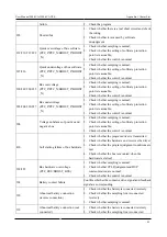
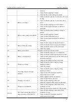
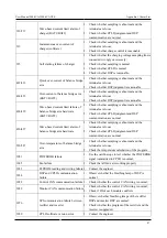
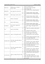
battery is not connected, the alarm "Battery disconnected" is a normal alarm), clear all abnormal alarms.
5.
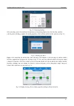
Step 5: turn on the rectifier and inverter. If the control bar of the monitoring display interface is gray and not
optional, first unlock it: click the password lock at the upper right corner of the display interface while the
system will pop up the unlocking window, and enter the password to unlock it (if the user does not change the
initial password, the initial password is "123456"), as shown in Fig. 5-1.
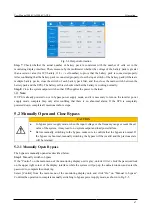
After unlocking, select [Control] from the main menu of monitoring display unit, click [Inv.On], and after
selecting and confirming, complete the starting operation of the rectifier and the inverter, as shown in Fig.
5-2.
6.
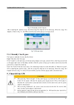
After completing the startup steps, check the energy flow diagram on the home page to confirm whether UPS
has completed the startup process, as shown in Fig. 5-3. The user can confirm whether the three-phase output
voltage and frequency of UPS are normal by the real-time data displayed in the monitoring and display
interface [System]→[Output], and test whether the effective value and frequency of the three-phase output
voltage are normal with a multimeter, as shown in Fig. 5-4.
7.
Check whether the actual number of battery pack is consistent with the number of cells set in the monitoring
display interface; Then, measure by the multimeter whether the voltage of the battery pack is greater than a
certain value (for 12V battery, 11.4v × cell number) to prove that the battery pack is connected properly.
After confirming that the battery pack is connected properly, close the input switch of the battery pack (if
there are multiple battery packs, close the switch of each battery pack first, and then close the main switch
between the battery pack and UPS). The battery self-test checks whether the battery is working normally.
Step 2:
Manually switch to bypass
1.
If the "Control" on the main menu of the monitoring display unit is gray, unlock it first: chick the password
lock on the upper right corner of the display interface while the system will pop up the unlock window and
enter the password to complete the unlocking.
2.
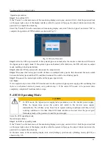
Select [Control] from the main menu of the monitoring display unit, and click “On” on “Manual to bypass”.
Confirm the operation to complete manually switching to bypass power supply mode, as shown in Fig. 5-5.
3.
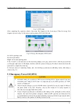
Check whether the manually switching to bypass is completed. The energy flow diagram of the home page
should be shown in Fig. 5-6 when UPS is switched to the bypass mode.
Step 3
: Close the system output switch. The UPS must be switched to the bypass mode before closing the system
output switch. After confirmation, manually close the system output switch of UPS. At this time, the maintenance
bypass and the static bypass of UPS are in parallel to supply power to the load.
Step 4
: Disconnect the maintenance switch
Step 5
: Manually switch from the bypass mode to the mains mode
1.
If the "Control" on the main menu of the monitoring display unit is gray, unlock it first: chick the password
lock on the upper right corner of the display interface while the system will pop up the unlock window and
enter the password to complete the unlocking.
2.
Select the "Control" from the main menu of the monitoring display unit, and click “Off” on “Manual to
bypass”". After completing the operation steps, check the energy flow diagram on the main page. When the
energy flow diagram is shown in Fig. 5-3, that is, UPS successfully switches from the bypass mode to the
mains mode.
Summary of Contents for EA990 Super
Page 1: ...200 kVA 1200 kVA ...

