background image


User Manual 200 kVA-1200 kVA UPS


                            5 Operation


67


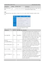
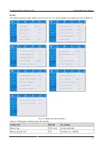
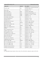
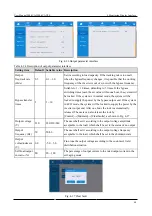
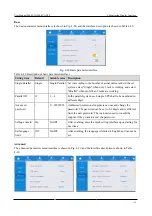
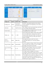
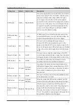
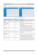
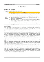
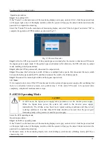
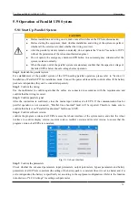
Fig. 5-4 Output information   

Step  7

:  Check  whether  the  actual  number  of  battery  pack  is  consistent  with  the  number  of  cells  set  in  the 

monitoring display interface; Then, measure by the multimeter whether the voltage of the battery pack is greater 
than a certain value (for 12V battery, 11.4v × cell number) to prove that the battery pack is connected properly. 
After confirming that the battery pack is connected properly, close the input switch of the battery pack (if there are 
multiple  battery  packs, close  the  switch of  each  battery  pack  first,  and  then  close  the  main  switch between the 
battery pack and the UPS). The battery self-test checks whether the battery is working normally. 

Step 8

:


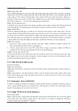
Close the system output switch so that UPS supplies the power to the load. 


Note:


If UPS is already powered on or in bypass power supply mode, and it is necessary to turn on the inverter power 
supply  mode,  complete  Step  only  after  confirmg  that  there  is  no  abnormal  alarm;  If  the  UPS  is  completely 
powered down, complete all mentioned-above steps. 

5.2 Manually Open and Close Bypass 


CAUTION   


In bypass power supply mode, when the input voltage or the frequency range exceeds the set 
value of the system, it may lead to no system output and load power failure. 


Before manually switching to the bypass, make sure to confirm that the bypass is normal. If 
the bypass is abnormal, manually switching the bypass will be invalid and the previous state 
will be retained. 

5.2.1 Manually Open Bypass 

The bypass is manually opened as described below:   

Step 1

: Manually switch to bypass 

If the "Control" on the main menu of the monitoring display unit is gray, unlock it first: chick the password lock 
on the upper right corner of the display interface while the system will pop up the unlock window and enter the 
password to complete the unlocking. 
Select  [Control]  from  the  main  menu  of  the  monitoring  display  unit,  and  click  “On”  on  “Manual  to  bypass”. 
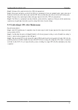
Confirm the operation to complete manually switching to bypass power supply mode, as shown in Fig. 5-5. 

Summary of Contents for EA990 Super

Page 1: ...200 kVA 1200 kVA ...

Page 2: ...products services or features described in this document may not be consistent with your purchase or use purpose Unless otherwise agreed in the contract we do not make any express or implied representations or warranties regarding the contents of this document Due to product version upgrade or other reasons the contents of this document will be updated from time to time Unless otherwise agreed thi...

Page 3: ...00 kVA 13 2 5 Optional Accessories 14 3 Installation 15 3 1 Installation Preparation 15 3 1 1 Site Preparation 15 3 1 2 Installation Tools 16 3 1 3 Preparation of Power Cables 17 3 1 4 Unpacking 19 3 2 Installation of Single UPS 20 3 2 1 Installation of UPS 20 3 2 2 Installation of Fixture 22 3 2 3 Installation of Battery 23 3 2 4 Connection of Power Cable 24 3 2 5 Communication Signal Interface 3...

Page 4: ...tart Up Parallel System 74 5 9 2 Shut Down Parallel System 75 5 9 3 Emergency Power Off EPO 75 5 9 4 Single UPS Exits from Maintenance 75 5 9 5 Add a Single UPS After Maintenance 76 6 Maintenance 77 6 1 Important Safety Information 77 6 2 Room Management 77 6 3 Preventative Maintenance 78 6 3 1 Monthly Maintenance 78 6 3 2 Quarterly Maintenance 78 6 3 3 Annual Maintenance 79 6 4 Battery Maintenanc...

Page 5: ...PS and the use and storage of equipment must follow the requirements set in the manual Avoid using the equipment in the environment with direct sunlight rain or dust containing electric charge During storage of UPS keep a safe distance around it to ensure ventilation Do not block the air vent while the system is running Do not allow liquids or other foreign objects into the UPS cabinet or case Bef...

Page 6: ...ture The batteries should be installed and stored in cool and dry environment Regular battery replacement can ensure that the UPS works properly and can ensure adequate backup time Check the screws of battery connection parts regularly to make sure they are tight The loosening must be tightened immediately Please do not short the positive and negative electrode of the battery otherwise it is possi...

Page 7: ...ided into standard model and full equipped model where 200 kVA 250 kVA 300 kVA models are full equipped models 400 kVA 500 kVA 600 kVA and higher power models include standard models and full equipped models The full equipped model includes a main switch a bypass switch an output switch and a maintenance bypass switch UPS model description is shown in Table 2 1 Table 2 1 Model description of UPS M...

Page 8: ...ance bypass switch main switch bypass switch and output switch 2 3 2 Operation Modes Normal mode The UPS rectifier is supplied with AC power by the mains and the inverter is supplied with DC power by the rectifier which provides continuous and uninterrupted AC power for the load Meanwhile the rectifier supplies a uniform charging current or floating charging voltage to the battery The schematic di...

Page 9: ... supply is restored the system will automatically switch back to the normal mode without any manual intervention and interruption of the power supply for the load If the mains is not restored after the battery backup time the system will automatically switch to bypass mode without interruption The operating principle of the battery mode is shown in Fig 2 4 Fig 2 4 Schematic diagram of battery mode...

Page 10: ... bypass range exceeds the ECO working range the power supply will be switched for the load from bypass power supply to inverter power supply ECO mode has higher system efficiency The operating principle of ECO mode is shown in Fig 2 6 Fig 2 6 Schematic diagram of ECO mode Mains battery combination mode When UPS is in normal operation the load power exceeds the supply capacity of the mains for a sh...

Page 11: ...A 300 kVA are fully equipped 400 kVA 500 kVA 600 kVA and higher power models include standard and fully equipped models The fully equipped models include main switch bypass switch output switch and maintenance bypass switch 2 4 1 System Structure of 200 kVA 250 kVA 300 kVA The appearance of 200 kVA 250 kVA 300 kVA models is shown in Fig 2 8 Fig 2 8 Appearance of 200 kVA 250 kVA 300 kVA models Main...

Page 12: ... plate is opened Fig 2 9 Functional parts of 200 kVA 250 kVA 300 kVA front view 1 Mains input switch 2 Bypass input switch 3 Bypass maintenance switch 4 System output switch 5 Smart card slot 6 Communication unit 7 Independent bypass module 8 Power unit 2 4 2 System Structure of 400 kVA 500 kVA 600 kVA The appearance of 400 kVA 500 kVA 600 kVAmodels is shown in Fig 2 10 1 2 3 8 7 6 5 4 Mains input...

Page 13: ...VA models are shown in Fig 2 11 where Fig 2 11 shows the state of UPS after the wiring cabinet and door panel of the bypass cabinet are opened if the user selects the fully equipped model of this power segment the wiring cabinet will be replaced by the distribution cabinet The appearance can be referred in the left side of the distribution switch shown in Fig 2 9 Fig 2 11 Functional parts of 400 k...

Page 14: ...s shown in Fig 2 12 Fig 2 12 Appearance of 750 kVA 900 kVA front view 1 Wiring cabinet 2 Bypass cabinet 3 Monitoring display unit 4 Power module 1 5 Power module 2 6 Power module 3 2 4 4 System Structure of 1000k 1200 kVA The appearance of 1000k 1200 kVA is shown in Fig 2 13 Fig 2 13 Appearance of 1000k 1200 kVA front view 1 Wiring cabinet 2 Bypass cabinet 3 Monitoring display unit 4 Power module ...

Page 15: ...n and other functions Lightning protector Used to prevent lightning current from entering the UPS from the power grid and protect the UPS Battery inspector Used to test the voltage and temperature of single battery and the charging and discharging current of the battery pack and communicate with host computer through MODBUS communication protocol Battery cold starting assembly When the mains is un...

Page 16: ...or environmental specifications Keep UPS away from water source heat source and inflammable and explosive articles Avoid installing UPS in the environment with direct sunlight dust volatile gases corrosive substances and excessive salt content It is forbidden to install UPS in the working environment with metal conductive dust The optimal operating temperature of valve controlled sealed lead acid ...

Page 17: ...nts Clip on ammeter Current test Cable drilling tool drill Drill Multimeter Test electrical connection and electrical parameter Insulating tape Electrical insulation Cross screwdriver Tighten screws Heat shrinkable T bush electrical insulation Levelling instrument Levelling Heat gun Heat heat shrinkable T bush Insulated monkey wrench Tighten and loosen bolts Electrician s knife Wire stripping Insu...

Page 18: ...4 580 722 Recommended cable diameter mm2 A B C N 1 120 1 150 1 185 2 120 2 150 Recommended terminal A B C N DT120 14 DT150 1 4 DT185 16 DT120 14 DT150 14 Battery input Nominal discharge current A of 4 x 12V battery 448 559 605 896 1118 Recommended cable diameter mm2 BAT BA T 1 185 2 95 2 95 2 185 2 240 Recommended terminal BAT BA T DT185 16 DT95 12 DT95 12 DT185 16 DT240 16 Ground wire Recommended...

Page 19: ... EPR insulation 90 PVC sheath flexible wire with copper conductor For same power supply is used for main circuit and bypass the input cable is conFig d according to the mains input cable The current value in the data calculated at rated voltage 230V The current value should be multiplied by 1 05 for rated voltage 220V and 0 96 for rated voltage 240V When the main load is nonlinear load the section...

Page 20: ...mended to conFig an air switch with leakage protection function When the input front end has multi stage load the specification of the circuit breaker conFig d in the front bus must be larger than that of the mains input air switch of UPS and the bypass input air switch When the output rear end has multi stage load the setting current of the circuit breaker installed on the rear level branch shall...

Page 21: ...lete items are shown in Table 3 7 Table 3 7 Complete items 1 UPS main equipment 2 RS232 communication cable 3 Communication light disk 4 Key 5 User manual 6 Warranty card UPS main equipment RS232 communication cable communication light disk key user manual warranty card In case of any damage or shortage please inform the carrier immediately Check whether the attached accessories are complete and c...

Page 22: ...must be lifted by the forklift otherwise the cabinet may be damaged When the forklift is used from the front and the arm length of the forklift should be larger than the width of the equipment The forklift shall have the arm with more than 200mm internal width and less than 700mm outer diameter for 200 kVA 250 kVA 300 kVA UPS and the arm with more than 700mm internal width and less than 1300mm out...

Page 23: ... of Fixture The fixture assembly is installed to provide anti seismic and shock proof function and may be selectively installed according to the installation environment The specific instillation procedures are given below Step 1 determine the installation location and set up the steel groove and other fixtures at the installation site according to the hole location and size diagram The hole locat...

Page 24: ... Step 5 fix the front and back bolts of the case to the ground with expansion bolts Step 6 reinstall the removed bottom baffle to the bottom side of the equipment 3 2 3 Installation of Battery During the installation design of UPS system please use batteries approved by supplier Without permission it is forbidden to use batteries of other brands because UPS is excluded from the warranty for damage...

Page 25: ... door of the input output wiring cabinet for the fully equipped model continue to remove the distribution switch baffle as shown in Fig 3 9 and Fig 3 10 Fig 3 9 Distribution switch baffle of full equipped 200 kVA 250 kVA 300 kVA Mains input Bypass input Maintenance bypass Output Distribution switch baffle ...

Page 26: ...ntry baffles at the top and bottom of the equipment and the front baffle of the wiring cabinet The position of the baffles is shown in Fig 3 11 Fig 3 11 Top and bottom cable ery baffle and front baffle of the wiring cabinet Mains input Bypass input Maintenance bypass Output Distribution switch baffle Top cable entry baffle Front baffle of wiring cabinet Bottom cable entry baffle ...

Page 27: ...removing the debris shield do not place any item on the ventilation grille of the cabinet 2 Lay input and output cables from the top or bottom of the cabinet to the UPS terminal The location information of the terminals is shown in Fig 3 12 Fig 3 13 Fig 3 14 Fig 3 15 Fig 3 16 and Fig 3 17 Fig 3 12 Terminal location in the wiring cabinet for standard 400 kVA 500 kVA 600 kVA front view UPS Section A...

Page 28: ...n the wiring cabinet for standard 400 kVA 500 kVA 600 kVA sectional view UPS Section B Section A Front side Rear side Battery Null line Battery Mains input Load output Bypass input Ground Front side Rear side Phase C Phase B Phase C Phase C Phase B Phase C Phase C Phase B Phase A ...

Page 29: ...lation 28 Fig 3 14 Terminal location in the wiring cabinet for full equipped 200 kVA 250 kVA 300 kVA right view UPS Mains input Null line Ground Null line Null line Battery Battery Load output Bypass input Main and bypass connection copper bar ...

Page 30: ...l location in the wiring cabinet for full equipped 200 kVA 250 kVA 300 kVA front view UPS Mains input Phase A B C from left to righ Bypass input Phase A B C from left to righ Load output Phase A B C from left to righ Null line Null line Ground Battery Battery Null line ...

Page 31: ...on 30 Fig 3 16 Terminal location in the wiring cabinet for full equipped 400 kVA 500 kVA 600 kVA right view UPS Mains input Null line Null line Null line Copper bar connecting main circuit and bypass Bypass input Battery Battery Load output Ground ...

Page 32: ...in circuit and bypass For the fully equipped mode it should be noted that after removing the copper plate connecting with the main circuit and the bypass before Steps 5 and 6 For the standard mode directly complete Steps 5 and 6 Same power supply for main circuit and bypass For the fully equipped mode without need to remove copper plate connecting with the main circuit and the bypass connect the A...

Page 33: ...l operation interface For parallel operation use parallel operation control cable to connect the parallel operation interface of each UPS into a ring The single UPS does not need to connect the parallel operation signal interface between the host When multiple UPS form a parallel operation system N parallel control cables the parallel operation of up to 4 sets of the equipment can be achieved are ...

Page 34: ...attery switch state Initial state is close and the open status means the battery switch opened and the close status means the battery switch closed Status detection UPS will give an alarm when the battery switch is disconnected Output switch state of distribution cabinet Initial state is close and the close status means the output switch of distribution cabinet closed and the open status means the...

Page 35: ...nitial state is close and the close status means non bypass power supply of UPS and the open status means the bypass power supply of UPS Output the status information of the bypass power supply Battery power supply Initial state is close and the close status means non battery power supply of UPS and the open status means the battery power supply of UPS Output the status information of the battery ...

Page 36: ... Prevent the operation failure of UPS due to abnormal communication By this function the UPS may be forcedly switched to the bypass BYP_COM Forcedly switch the bypass enabling circuit EPO_NO Remote EPO opened normally Remote EPO function EPO_NC Remote EPO closed normally EPO_COM Remote EPO public terminal VCC 48V Externally connect with the positive pole of 48V battery Used for external connection...

Page 37: ... status inspection of the single battery CAN Connect the battery inspector by CAN to achieve the status inspection of the single battery NET interface NET Connect the local host through NET network port to debug and conFig UPS Battery temperature sensor interface BAT TEMP Connect the battery temperature sensor through RJ45 interface to realize the detection of battery temperature USB device interf...

Page 38: ...properly install the AC input cable and battery cable of each UPS for the parallel system according to 3 2 4 Step 2 ground the individual equipment of each parallel system separately Step 3 connect the mains input of UPS to mains 1 and 2 respectively and connect the batteries to the battery pack 1 and the battery pack 2 respectively Connect the bypass input and the load output in parallel and resp...

Page 39: ...ation Use same length and specification of the power cable as far as possible so that the bypass mode can achieve the current sharing effect See Fig 3 20 Fig 3 20 Bypass current equalizing cable connection 3 3 2 Connection of Control Cable Connection of parallel control cable Use the parallel control cable to connect the parallel interface of each UPS in the parallel system into a loop Taking the ...

Page 40: ...te EPO control wiring diagram of the parallel system that is when EPO isperformed on one of the UPS other UPS are normally running Fig 3 22 EPO separate control wiring diagram of the parallel system Fig 3 23 is the EPO general control wiring diagram of the parallel machine system that is all UPS in the parallel machine system are shut down in an emergency when EPO operation is carried out on the p...

Page 41: ...t is shown in Fig 3 25 Fig 3 25 wiring diagram of forced bypass dry contact 3 4 Installation Inspection The inspection items and acceptance criteria are shown in Table 3 9 Table 3 9 Inspection items and acceptance criteria No Inspection items Acceptance criteria 1 Inspect whether the system configurations are consistent with the shipped those The field system model and number of units should be co...

Page 42: ... should be labeled and the label should be concise and easy to understand 6 Check whether the ground wire of UPS is connected to the ground wire row of the machine room and whether the ground wire connection is reliable Lead to the grounding bar in the machine room and connect firmly 7 Check each cable connection Check for correct cable connection according to the circuit diagram 8 Check whether t...

Page 43: ...ple the position of the monitoring panel is shown in Fig 4 1 Fig 4 1 Monitoring panel 4 1 1 Appearance of Monitoring Panel The appearance of the monitoring panel is shown in Fig 4 2 Fig 4 2 Schematic diagram for monitoring display unit panel LED indicator light LCD display touch screen 4 1 2 LCD and Indicator Lamp The monitoring display unit displays all kinds of operation information and alarm in...

Page 44: ...ogging in the user password only some menu functions are displayed Therefore the users should change and set UPS according to the actual situation The menu structure of the monitoring display interface is shown in Fig 4 3 Fig 4 3 Menu structure 4 2 1 Starting for First Time Upon starting for first time or restarting after restoring factory setting Quick Settings are available as shown in Fig 4 4 T...

Page 45: ...Interface 44 Fig 4 4 quick settings Enter the home page after the quick setting 4 2 2 Home The monitoring home page is divided into three parts main menu energy flow diagram and status bar The main interface is shown in Fig 4 5 Fig 4 5 Home interface 3 1 2 ...

Page 46: ...ns the current alarm and Off means no alarm currently HMI communication status On indicates normal communication between HMI and monitoring module Off indicates abnormal communication between HMI and monitoring module USB connection state On indicates that the USB device is connected normally and Off indicates that the USB device is not connected or the connection is abnormal Password login logout...

Page 47: ...ly The interface description is shown in Table 4 5 Fig 4 7 Input interface Table 4 5 Description of input interface Display item Description Voltage V Phase voltage of mains input Current A Phase current of mains input Frequency Hz Frequency of mains input Bypass The bypass input menu interface is shown in Fig 4 8 and the interface description is shown in Table 4 6 Fig 4 8 Bypass interface Table 4...

Page 48: ...atus Current battery status standby charging discharging Remaining cap Current residual battery capacity Backup time min Estimated discharging time of battery at current load Temperature Current operation temperature of battery battery temperature sensor is required and NA is displayed when not connected SOH Percent of battery health Module The built in information of each power module is displaye...

Page 49: ...nput apparent power of selected module Output volt V Output phase voltage of selected module Output curr A Output phase current of selected module Output freq Hz Output frequency of selected module Out act pow kW Output active power of selected module Out appa pow kVA Output apparent power of selected module Out reac pow kVar Output reactive power of selected module Out pow factor Ratio of active ...

Page 50: ...apparent power of UPS Statistics The statistical menu interface is shown in Fig 4 12 and the interface description is shown in Table 4 10 Fig 4 12 Statistical interface Table 4 10 Description of statistical interface Display item Description Bypass runtime min Accumulative running time of UPS in the by pass output state Inv runtime min Accumulative running time of UPS in the inverter output state ...

Page 51: ...ystem MCU version program version of monitoring system Bypass version program version of power bypass system PFC1 version program version of power rectifier system Inv 1 version program version of power inverter system 4 2 4 Alarms In the Alarms information interface you can select Active alarm Fault record Status record and Operating record from the second level menu in the lower left corner The ...

Page 52: ...ing and the time is not displayed History record The history log is divided into Fault record Status record and Operating record Taking the fault record as an example the history log interface is shown in Fig 4 16 and the interface description is shown in Table 4 13 Fig 4 16 History log interface Table 4 13 Description of history log interface Display item Description No Record number The records ...

Page 53: ...face description is shown in Table 4 14 Fig 4 17 On Off interface Table 4 14 Description of On Off interface Control item Description System On Off Including Inv On Shut to byp Shutdown Gray when clicking is invalid Manual to bypass Including On and Off Gray when clicking is invalid If the bypass is abnormal the UIPS does not switch to the bypass Maintenance The maintenance menu interface is shown...

Page 54: ...ort history export Excel document import LOGO import boot animation Firmware upgrade The firmware upgrade menu interface is shown in Fig 4 19 and the interface description is shown in Table 4 17 Fig 4 19 Firmware upgrade interface Table 4 17 Description of firmware upgrade interface Display item Description Chip Display online chip name Curr ver Display the current program version of the chip New ...

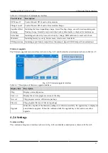
Page 55: ...ment Auto lock 5min 0 30min The time required for screensaver 0 indicate no screensaver User password 123456 0 99999999 The users can change the password password can be set to 1 to 8 digits or letters or their combination Remote control Off On Off For the user version MODBUS protocol 03 function code settings table if enabled the control items Buzzer Off System on off and system clock in the tabl...

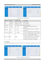
Page 56: ...one Odd Even IP address allocation Auto DHCP Auto DHCP Static IP allocation mode IP address subnet mask gateway and other settings are set for the network port When UPS connects to the router it can be set to dynamic and the router will automatically allocate the address When UPS is connected directly to the computer it is necessary to select static allocation and set the IP address of UPS in the ...

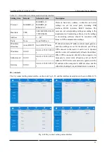
Page 57: ...ontact shall be set and if the dry contact is not used set to None otherwise it will affect the normal operation of UPS Bypass The bypass parameter menu interface is shown in Fig 4 23 and the interface description is shown in Table 4 21 Fig 4 23 Bypass parameter interface Table 4 21 Description of bypass parameter interface Setting item Default Selectable value Description ECO voltage range 10 5 6...

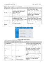
Page 58: ...itable for input sources with better performance such as mains and AC voltage source etc in which the input THDi is better Inter rack pow mdl start delay s 2 2 120 By setting the start delay of inter rack intelligent generators during the process of switching battery inverter to main inverter for power supply the time interval of each rack switching to main power supply in turn is controlled to re...

Page 59: ...menu interface is shown in Fig 4 25 and the interface description is shown in Table 4 23 Fig 4 25 Battery parameter interface Table 4 23 Description of battery parameter interface Setting item Default Description Battery type VRLA batt Setting prohibited Battery capacity Ah 100 Settable to 5 3000Ah ...

Page 60: ...e Settable to Disable Enable Remain cap warning thresh 20 Settable to 5 50 SOH 100 Settable to 0 100 Chg cur limiting coef C10 0 10 Settable to 05 0 30 C10 Cell float voltage V cell 2 25 Settable to 2 23 2 27V cell Cell equalized volt V cell 2 35 Settable to 2 30 2 40V cell Cell EOD volt warn increment V 0 10 Settable to 0 0 20V Battery unlock time min 15 Settable to 1 60min Max batt dis time h 24...

Page 61: ...o supply the power by the bypass output end If the system in ECO mode the system will be locked to supply the power by the inverter output end After one hour the lock is automatically released The users can also release the lock by Control Maintain Clear faults as shown in Fig 4 27 Output voltage V 230 220 230 240 The user shall set it according to the output voltage amplitude acceptable to the lo...

Page 62: ...ore than 2 racks are working Parallel ID 1 1 4 In the parallel system each single UPS shall to be numbered in different digit Advanced password 0 99999999 Authorized professional engineers can use and change the password The password can be set to 1 8 digits and is different from the user password The customers need to consult the supplier if they want to know the password Settings wizard On On Of...

Page 63: ...ee the derating description of technical parameters in chapter 8 for details Cabinet master slave Master Master Slave This setting item does not need to be set and is automatically assigned by the system upon parallel operation Charger hibernate Enable Disable Enable If it is set to Enable the charger will enter the sleep status when it meets the sleep condition if it is set to disabled the charge...

Page 64: ... the system cannot supply the power in the bypass mode Impact to bypass On On Off If it is set to be on when the output voltage of the UPS system is decreased quickly due to impact load the system will supply the power in the bypass mode for a short time EPO function On On Off Set whether to enable emergency shutdown function according to the actual requirements of customers EPO action To bypass T...

Page 65: ...00 00 00 Not settable Automatically generate the warranty time limit according to the installation time and quality warranty period When the system time exceeds the warranty time limit the status bar of the home page displays the information on the warranty time limit UPS installation time 2018 01 01 00 00 00 Arbitrary value Click the pop up to confirm the update to the current time UPS warranty t...

Page 66: ...this chapter are the accessories of full equipped models If the user chooses a full equipped UPS model complete all following steps If the user chooses the standard model UPS the specific operation steps shall be determined according to the actual site environment and shall be conducted under the guidance of the authorized engineers Step 2 Close the mains input switch and the bypass input switch T...

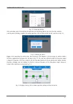
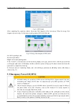
Page 67: ...g the startup steps check the energy flow diagram on the home page to confirm whether UPS has completed the startup process as shown in Fig 5 3 The user can confirm whether the three phase output voltage and frequency of UPS are normal by the real time data displayed in the monitoring and display interface System Output and test whether the effective value and frequency of the three phase output v...

Page 68: ...ply mode complete Step only after confirmg that there is no abnormal alarm If the UPS is completely powered down complete all mentioned above steps 5 2 Manually Open and Close Bypass CAUTION In bypass power supply mode when the input voltage or the frequency range exceeds the set value of the system it may lead to no system output and load power failure Before manually switching to the bypass make...

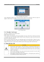
Page 69: ...ontrol from the main menu of the monitoring display unit and click Off on Manual to bypass After completing the operation steps check the energy flow diagram on the main page When the energy flow diagram is shown in Fig 5 3 that is UPS successfully switches from the bypass mode to the mains mode 5 3 Turn Off the UPS CAUTION When selecting Shut to bypass if the system bypass is normal and the UPS i...

Page 70: ...f each battery pack Step 5 Disconnect the mains input switch and the bypass input switch Note If it is required only to turn off the UPS inverter and turn the system to bypass power supply after confirming that there is no abnormal alarm at present only perform step 1 If the entire UPS needs to be powered down completely complete all mentioned above steps 5 4 ECO Operating Mode CAUTION In ECO mode...

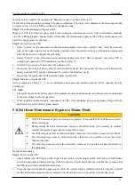
Page 71: ... unit click Settings Advanced Working mode Normal as shown in Fig 5 8 5 5 Emergency Power Off EPO CAUTION In default setting the operation of EPO causes switching UPS to bypass output to prevent accidental power outages If UPS have no output directly by the EPO operation set EPO action to Shutdown After closing the emergency power off EPO button it possible to cause no output of UPS and the power ...

Page 72: ...lease refer to Steps 5 7 in Section 5 1 Turn on the UPS for specific operation 5 7 Switch to Maintenance Bypass CAUTION Only authorized and qualified maintenance personnel can perform UPS repairs or maintenance under the maintenance bypass Operation of switching the maintenance bypass must be carried out in strict accordance with the following steps otherwise it is possible to cause electric shock...

Page 73: ...he UPS After completion of Steps 1 3 do no dissemble and replace the machine module till the capacitor is fully discharged Note 1 The mains input and the battery input of the equipment must be disconnected and the capacitor is discharged to the safe voltage before the operation 2 When touching internal module components of UPS wear insulating gloves or measure voltage with the multimeter to preven...

Page 74: ...her the voltage of the battery pack is greater than a certain value for 12V battery 11 4v cell number to prove that the battery pack is connected properly After confirming that the battery pack is connected properly close the input switch of the battery pack if there are multiple battery packs close the switch of each battery pack first and then close the main switch between the battery pack and U...

Page 75: ... independent they can be connected separately Step 2 Confirm the wiring Use the multimeter to confirm again that the cables are connected in accordance with the requirements and confirm that the wiring is correct Step 3 Confirm parallel signal After the connection is confirmed close the mains input switches of all UPS If the communication line for parallel operation is not connected Parallel line ...

Page 76: ... each UPS and check whether all UPSs are normally switched to the battery mode through the home of the monitoring panel 2 Close the mains input switch of each UPS enable Shut to bypass and observe whether all UPSs can normally switch to the bypass mode through the home of the monitoring panel Step 10 Close the main output switch Switch each UPS back to the inverter mode then close the main output ...

Page 77: ...ormed after the capacitor voltage falls below the safe voltage 5 9 5 Add a Single UPS After Maintenance Operation procedures Step 1 After UPS maintenance is completed close the mains input switch bypass input switch output switch and battery switch of UPS Step 2 Confirm that the option of Single Parallel in the basic parameter setting is set to Parallel according to Step 5 1 power on the equipment...

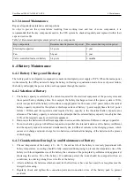
Page 78: ...pack will not be released Therefore do not touch any internal area of the battery pack There is always voltage inside the battery pack If you need to replace the battery contact your supplier If it is really required to maintain the battery pack please refer to the battery maintenance instructions in the battery manufacturer s operation manual or contact your maintenance representative When operat...

Page 79: ...f UPS and check and record increase and decrease of the load regularly Check and record the operating environment temperature and humidity of UPS Check that the UPS parameters are conFig d correctly Fill in UPS maintenance report form classify and deal with abnormal situation and alarm Export alarm information from the system and analyze the alarm information and the output alarm analysis report 6...

Page 80: ...battery power supply time after AC power failure 200Ah and the required actual required battery capacity is the theoretical battery capacity plus allowance The battery capacity is selected in the principle that the selected battery capacity is not higher than 120 of the required capacity of electrical equipment 2 Don not use the batteries with different capacities in series and the batteries of di...

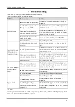
Page 81: ...ion facilities for the machine room to ensure the normal temperature of the machine room Wave based current limit and over current failure of inverter Check the failure record list in the display panel to see if there is any failure If yes access the control interface to clear the failure Power unit failed Replace the power unit AC system failing to switch to battery mode Wave based current limit ...

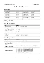
Page 82: ...range of input voltage 260 460 Vac Variable range of input frequency 40 70 Hz Input power factor 0 99 Battery voltage 480 Vdc 456 468 492 504 Vdc optional Cell number 12 V x 40 cells 38 39 41 42 optional 8 2 2 UPS System Output Output Parameters Output phase number Three phase five wires 3Φ N PE Rated output voltage 380 400 415 Vac Output voltage regulated accuracy 1 Accuracy of output frequency M...

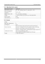
Page 83: ...ection grade IP 20 Noise level at 1 m 70 dB 8 2 4 System System Maximum of parallel UPSs 4 Switching time 0 ms Protection function Phase loss protection phase sequence error protection short circuit protection overload protection overwet protection battery undervoltage protection output voltage protection fan failure protection Communication interface Standard CAN RS232 RS485 USB LBS RJ45 dual sma...

Page 84: ... input phase sequence Check whether the phase sequence of the mains is inverted the sampling line is inverted and the sampling is normal 124 Abnormal input phase lock Check whether the phase sequence of the mains is inverted and the program is abnormal 514 Soft starting of PFC failed 1 Check whether CPLD is driven 2 Check whether the conditions are satisfied by the PFC soft start up program 112 11...

Page 85: ... DSP and CPLD communication failure 1 Check whether the communication circuit is abnormal 2 Check whether the communication part of the program is abnormal 512 Failure of auxiliary power supply 1 1 Check the open circuit of the fuse 2 Check the 15V voltage of the power panel is abnormal 3 Check whether the power supply of the fan on the power board is abnormal 4 Check the software for testing and ...

Page 86: ... setting of software protection point is reasonable 3 Check whether the control is normal 206 Voltage unbalance of positive and negative bus 1 Check whether sampling is normal 2 Check whether the setting of software protection point is reasonable 3 Check whether the control is normal 430 Soft starting failure of bus hardware 1 Check whether the program driver is transmitted 2 Check whether the har...

Page 87: ...he dry contact 300 Battery overtemperature 1 Check whether the battery is over temperature 2 Check whether the monitoring sampling is normal 3 Check whether communication is abnormal between the monitor and DSP 4 Check whether DSP processing is abnormal 320 Charger overvoltage 1 Check whether the battery charging voltage sampling is normal 2 Check the program 341 Overvoltage failure of charger har...

Page 88: ...and the terminals are loose 2 Check whether CPLD judgment and DSP communication are normal 436 437 Wave based current limit alarm of balance bridge arm hardware 1 Check whether sampling is abnormal and the terminals are loose 2 Check whether CPLD judgment and DSP communication are normal 526 527 Over temperature of balance bridge arm 1 Check whether sampling is abnormal and the terminals are loose...

Page 89: ...drive signal and state feedback signal 2 Check whether the contactor is stuck 1000 1001 1002 Inverter over temperature A B C 1 Check that all fans are working properly 2 Check whether the IGBT driver is normal 3 Check whether inductance current sampling is normal 4 Check whether temperature sampling is normal 1048 1049 1050 Wave based current limit failure of inverter A B C 1 Check for overload or...

Page 90: ...ter overload alarm 1 Check for overload 2 Check whether the output voltage inductance current and bus voltage sampling is normal 707 105 inverter overload time out 1 Check for overload 2 Check whether the output voltage inductance current and bus voltage sampling is normal 708 110 inverter overload time out 1 Check for overload 2 Check whether the output voltage inductance current and bus voltage ...

Page 91: ...lower limit of ECO 662 ECO frequency over voltage Bypass beyond upper and lower limit of ECO 663 ECO frequency under voltage Bypass beyond upper and lower limit of ECO 648 Quick over voltage of bypass Abnormal bypass or RCD load overload 639 Quick power failure of bypass Load impact or quick power failure 651 Quick under voltage of bypass Load impact or quick power failure 700 701 702 Effective va...

Page 92: ...r of the pull down resistor of CAN communication bus is normal and the inverter DSP of UPM is halted abnormally or powered down 1200 Abnormal CAN communication between parallel system boards 1 Communication failure Check whether the connecting wire is disconnected the wire jumper of the pull down resistor of CAN communication bus is normal and the inverter DSP of UPM is halted abnormally or powere...

Reviews: