User Manual 200 kVA-1200 kVA UPS
4 Monitoring Display Interface
56
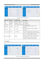
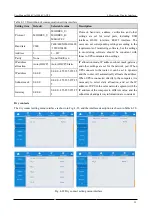
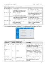
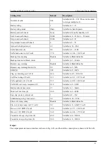
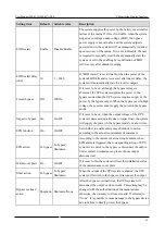
Table 4-20 Description of dry contact setting interface
Setting item Default Selectable value
Description
DI_1~DI_6
No
None/Battery ground fault/D.G.mode/
Battery breaker/PDC output breaker/
PDC mainten. breaker/
PDC bypass breaker/
AC SPD switch/Ex.transfor.overtemp.
For 6 external input dry contact
interfaces, when configuring dry contact,
the relevant dry contact shall be set, and if
the dry contact is not used, set to "None",
otherwise it will affect the normal
operation of UPS.
DO_1~DO_6 No
Critical alarm/Minor alarm/Bypass power
supply/Battery power supply/
Low batt.volt.(DOD)/Low batt.volt.(EOD)
/D.G.control/Batt. breaker release/
Bypass fault/Fan fault/
Time-share power down
For 6 external output dry contact
interfaces, when configuring dry contact,
the relevant dry contact shall be set, and if
the dry contact is not used, set to "None",
otherwise it will affect the normal
operation of UPS.
Bypass
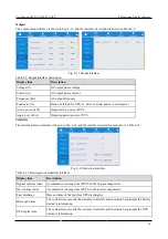
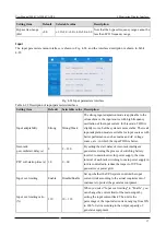
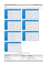
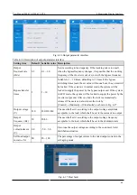
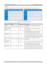
The bypass parameter menu interface is shown in Fig. 4-23, and the interface description is shown in Table 4-21.
Fig. 4-23 Bypass parameter interface
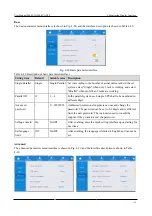
Table 4-21 Description of bypass parameter interface
Setting item
Default Selectable value
Description
ECO voltage range
(%)
±10
±5/±6/±7/±8/±9/±10
When the deviation of bypass voltage relative
to the rated voltage exceeds the set value, the
system determines that ECO voltage is
abnormal, and the system turns the inverter for
power supply. Note that the ECO frequency
range cannot be greater than the bypass
frequency range. For example, if the bypass
frequency range is set as ±2HZ, then the ECO
frequency range can only be set to ±1HZ and
±2HZ.
ECO freq. range
(Hz)
±2
±1/±2/±3
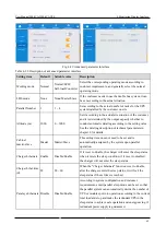
Max. bypass
voltage (%)
+15
+10/+15/+20/+25
The maximum settings range from 88V to
276V. Generally set to the the acceptable
voltage range of the user’s electrical
equipment .
Min. bypass voltage
(%)
-20
-10/-20/-30/-40/-50/-60
Summary of Contents for EA990 Super
Page 1: ...200 kVA 1200 kVA ...


