22
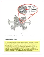
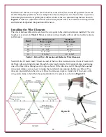
Install the 78" and the 112" ropes across the front of the beam, tied around the spreaders where the
smaller fiberglass spreader section is clamped into the next larger section. Secure these ropes into a
horizontal position with out pulling the middle sections of the two spreaders together as shown in
Figure 19
. These two spreaders will now remain straight when the wire elements are strung around
and tied and straightened into position with tension.
Installing the Wire Elements
The precut and assembled wire sets have the wire guide tubes and ring terminals installed. The wire
lengths are as shown in
Table 2
. Minor variations in these lengths will not adversely affect antenna
performance.
Band
Driven Elements (2)
Wire Length
Reflector
Wire Length
20
17' 10-1/2"
33' 10"
17
13' 10-1/4"
26' 3"
15
11' 10"
22' 6"
12
9' 11-1/2"
19'
10
8' 8-3/4"
16' 8-3/4"
Table 2 - Driven Wire Elements and Reflector Wire Elements
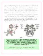
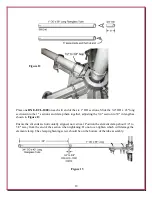
Start with the 20 meter band. Thread one end of the two driven element wires (front of beam) with
the black tubes and ring terminals through the previously installed wire guide clamps, positioning
one of the black tubes through each clamp as shown. If the tube does not fit through the loosened
wire guide clamp, you may need to nudge the installed clamp opening slightly (see below). The
tubes are pre-installed on the wire sets. Once the tubes are in place, tighten the Nyloc nuts on the
wire guides clamp to hold the tubes perpendicular to it's spreader as shown in
Figure 20
.
Figure 20


