background image

24 

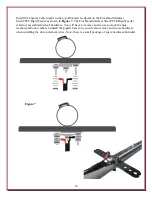
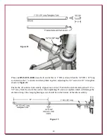
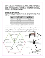
The 20 meter reflector (rear of beam) wire with black tubes and ring terminals is threaded through 
the p-clamps used for the reflectors in the same manner as the driven element. Thread the wire and 
black tubes through and position one tube in each p-clamp.  


Figure 22 

 
Repeat the sequence to install the 17 meter driven element wires and the 17 meter reflector wire. 
The coaxial cable pigtail is only installed on the 20 meter 
feed. 
 
Repeat the sequence to install the 15 meter driven element 
wires and the 15 meter reflector wire.  
 
Repeat the sequence to install the 12 meter driven element 
wires and the 12 meter reflector wire.  
 
Repeat the sequence to install the 10 meter driven element 
wires and the 10 meter reflector wire.  


Summary of Contents for HEXXAGONAL BEAM Mark 2

Page 1: ...TAP 2 DXE HEXX 1TAP 2 DXE HEXX BEAM MARK2 INS Rev 6 DX Engineering 2016 1200 Southeast Ave Tallmadge OH 44278 USA Phone 800 777 0703 Tech Support and International 330 572 3200 Fax 330 572 3279 E mail...

Page 2: ...l Hub Assembly Instructions US Patent No D605 184 9 Working with Fiberglass 10 Center Post Assembly 11 5 Band Stainless Steel PTFE Rigid Feeder System US Patented British Patented 13 Installing the Ce...

Page 3: ...tent No D605 184 The cast aluminum Hexxagonal Beam Hub provides a superior mounting platform with built in v saddle clamping channels and all stainless steel v bolts and hardware are included The DX E...

Page 4: ...providing a far stronger heavy duty attachment for the mast For the rest of the antenna frame high quality stainless steel element clamps rigidly hold the telescoping fiberglass sections at the correc...

Page 5: ...lements no lossy coils or traps Five Band Stainless Steel PTFE Rigid Feeder System US Patent No 8 669 91 US Patent No D624 060 British Patent No GB248003 B Requires no matching network direct single 5...

Page 6: ...Connection Assembly w cushioned P Clamps mounted on Stainless Steel Band Clamps 1 Center Post Rope Connection Assembly includes the following parts 1 DXE MPH 1 Multi Purpose Hub 1 5 3 1 4 20 x 1 25 St...

Page 7: ...seizing of stainless steel hardware TES 2155 3M Temflex 2155 Rubber Splicing Tape TES 06132 Scotch Super 33 Tape The DXE FCC050 H05 A Feedline Current Choke and the DXE BMB 1P Balun Mounting Kit for...

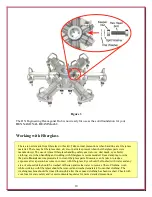
Page 8: ...s parts were manufactured The use of typical fiberglass handling safety gear gloves dust mask eye shield clothing etc when handling and working with fiberglass is recommended Use a damp rag to wipe th...

Page 9: ...at Washer 6 1 4 20 Stainless Steel Split Washer Insert the twelve Stainless Steel V Bolts over the cast V Saddles as shown in Figure 2 Figure 2 Jet Lube SS 30 Anti Seize or Never Seez should be used t...

Page 10: ...c when handling and working with fiberglass is recommended Use a damp rag to wipe the parts Do not use compressed air to clean fiberglass parts Measures can be taken to reduce exposure after a person...

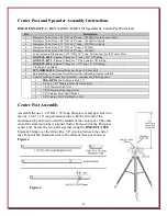
Page 11: ...acron Polyester Rope 100 Foot Roll 6 Spreader Rope Connection Assemblies with cushioned p clamps installed 1 Center Post Rope Connection Assembly includes the following parts 1 DXE MPH 1 Multi Purpose...

Page 12: ...of these bolts is maintained by tightening the keeper nuts only until the split washers are flat while keeping the mast mount bolts from turning further Once assembled you can use a customer supplied...

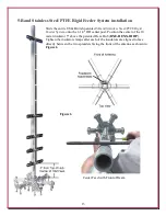
Page 13: ...eder System onto the 1 1 4 OD center post Position the center of the 10 meter insulator 5 above the patented Hexx Hub DXE HEXX 1HBP Tighten the insulator clamps after each of the insulators are aligne...

Page 14: ...e Five Band Stainless Steel PTFE Rigid Feeder is factory assembled with all hardware You will have to remove and re use some of the nuts washers and lock washers to install the pigtail Later on you wi...

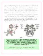
Page 15: ...s shown in Figure 9 Orient this hub so its vertical holes are facing between every other spreader Tighten the hub hardware carefully so the center post and the hub are concentric space between the cen...

Page 16: ...ainless steel band clamps included with the DXE BMB 1P One clamp is located below the 20 meter feed point clamp and the lower band clamp is located above the 17 meter element clamp as shown in Figure...

Page 17: ...For ease of assembly and adjustment of the spreaders each element clamp tightening nut should be under the spreader as you look down on the antenna Insert a 3 4 OD x 5 long fiberglass reinforcement t...

Page 18: ...r adjusting the 3 4 section to 39 in length as shown in Figure 13 Ensure the slit ends are horizontally aligned not vertical Position the element clamp about 1 4 to 3 8 away from the end of the sectio...

Page 19: ...Figure 15 and tighten the DXE ECL 0875 clamp Position the element clamps about 1 4 to 3 8 away from the end of the section when tightening Do not over tighten which will damage the element clamp The c...

Page 20: ...ng The dimensions indicated include extra length for knots Upon completion of the antenna excess rope may be trimmed and re melted Cut seven pieces of spreader support rope 144 in length 12 ft Cut one...

Page 21: ...rope attachment holes on this hub Figure 18 Repeat this process on the spreader on opposite sides of the antenna until all six spreaders are secured in their final position Each spreader end will be...

Page 22: ...se lengths will not adversely affect antenna performance Band Driven Elements 2 Wire Length Reflector Wire Length 20 17 10 1 2 33 10 17 13 10 1 4 26 3 15 11 10 22 6 12 9 11 1 2 19 10 8 8 3 4 16 8 3 4...

Page 23: ...Five Band Stainless Steel PTFE Rigid Feeder Hardware previously installed to hold the coaxial pigtail is removed and re used Refer to Figure 21 for the hardware sequence Hardware Loose Hardware instal...

Page 24: ...ure 22 Repeat the sequence to install the 17 meter driven element wires and the 17 meter reflector wire The coaxial cable pigtail is only installed on the 20 meter feed Repeat the sequence to install...

Page 25: ...cal Spacing Length 20 23 1 2 17 18 15 15 1 2 12 13 1 4 10 11 3 4 Table 3 Figure 24 Note Although not normally required for installations 35 feet above ground for lower antenna installations minor adju...

Page 26: ...accomplish sufficient hold If the optional Feedline Current Choke was not installed connect a coaxial cable RG 213 or equivalent feedline to the included double female SO 239 UHF to UHF adapter instal...

Page 27: ...e frequency range Lower frequency SWR dips are normal for antennas installed below 35 feet If any adjustments are desired they should be done incrementally and simultaneously with a small changes of d...

Page 28: ...rimped hand soldered and special weatherproof adhesive shrink tubing installed for a long lasting precision feedline assembly The coaxial cable center conductor connection has red shrink tubing on the...

Page 29: ...m in place and do not tighten 5 Band positions Position depends on your band choice Choose one Mount the Single Band Insulator Center Feed Clamp Assembly on the vertical post in the position for the c...

Page 30: ...d in this kit Band Driven Elements 2 Wire Length Reflector Wire Length 20 17 10 1 2 33 10 17 13 10 1 4 26 3 15 11 10 22 6 12 9 11 1 2 19 10 8 8 3 4 16 8 3 4 Note Although not normally required minor a...

Page 31: ...length jumpers and special element dimensions which may vary from the dimensions in this manual The process of creating a two band antenna has not been evaluated by DX Engineering The owner of the an...

Page 32: ...per installation damaged from severe weather including floods or abnormal environmental conditions such as prolonged exposure to corrosives or power surges or by the performance of repairs or alterati...

Reviews: