25
Figure 23
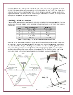
is a side view for reference showing the wire elements installed.
Figure 23
The previously cut ropes (Table 1) for the element spacers are installed for each band as shown in
Figure 24
. The critical spacing final measurements are shown in
Table 3
.
Band
Element Spacer Ropes
Critical Spacing Length
20
23-1/2"
17
18"
15
15-1/2"
12
13-1/4"
10
11-3/4"
Table 3
Figure 24
Note:
Although not normally required for installations 35 feet above ground, for lower antenna
installations, minor adjustments, by trimming of a particular wire driven element and/or reflector
element wires may be needed to minimize the SWR. Additional information on tuning is found in
the section: "SWR Testing" at the end of these assembly instructions. Additional Ring Terminals
are supplied for this purpose.

