2-6
12H-M12M0-0309-0
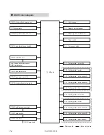
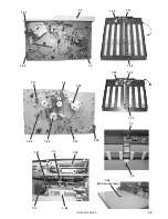
1-1. MC Unit
[Part No.: 12H-8003X (DF-920), 12H-8602X (DF-915)
Part name: Main unit]
Located inside the operating side cover (below the control panel) and functions to control the whole unit. Mounted with
a 1M-byte ROM in the microprocessor which performs control of the whole unit. This board is also mounted with one
256-byte EEPROM, as well as the driving circuits for the DC motor and clutch.
Converts DC +24 V power input from the switching power supply to +5 V, +6.3 V, and +12 V.
The power supply used by this unit is DC +5 V and DC +6.3 V (panel displays) for the control system (ICs,
sensors, etc.), and DC +24 V for the load system (motors, clutches).
Note
Note
1-2. Control Panel
[Part No.: 12H-9011X (DF-920), 12H-9052X (DF-915)
Part name: Control panel unit]
Composed of key switches, 16-character
×
2-line LCD (DF-920 only), 7-segment display, and various display LEDs
required for operating this unit.
1-3. Paper Feed Inlet Sensor
[Part No.: 11G-8052X (Light-emitting), 11G-8051X (Light-receiving)
Part name: Photosensor]
Uses a separation type photointerrupter. Located about 60 mm (2.36") inside from the paper feed ring to detect paper
fed.
If the sensor is not blocked even though the paper feed clutch has been driving for more than a certain distance
(number of pulses) after it turned ON, it is determined as paper feed error. Likewise, if the sensor continues to be
blocked even though the paper feed clutch has been driving for more than a certain distance (number of pulses) after
it was blocked, it is determined as paper jam.
As the paper folder processing speed can be changed, the sensor ON/OFF timing is based on distance (number
of pulses) and not time.
Note
Note
1-4. Paper Ejection Outlet Sensor
[Part No.: 11G-8052X (Light-emitting), 11G-8051X (Light-receiving)
Part name: Photosensor]
Uses a separation type photointerrupter. Located about 50 mm (1.97") inside from the stacker roller home position to
detect paper ejection.
If the sensor is not blocked even at the timing for the paper to be ejected, or continues to be blocked even though the
paper ejection clutch has been driving for more than a certain distance (number of pulses) after it was blocked, it is
determined as paper jam.
1-5. Paper Switch
[Part No.: 054-10326
Part name: Paper switch]
Uses a photointerrupter. Incorporated inside the paper feed tray to detect the presence of paper.
1-6. Top Cover Switch
[Part No.: 054-10248
Part name: Microswitch]
Uses the normal open microswitch. Incorporated inside the non-operating side frame. The contact is established
when the cover is closed.
Connected to the relay mounted on the MC unit. As the relay contact is established to the DC +24 V supplied to each
motor, when the contact of the cover switch or folding plate set switch is opened, power supply to each motor is cut off.
Therefore if the top cover is open, the unit cannot start. The unit also stops suddenly when the cover is opened while
operating.


