1-27
12H-M12M0-0309-0
2-5-3. Paper ejection roller lever unit
The basic configuration of this unit is more or less the same as the DF-520N.
If the paper ejection roller lever unit has been removed during the replacement of the drive motor, attach it using the
following procedure.
q
Apply a very small amount of oil to the area where the
drive shaft of the paper ejection roller lever unit and
bearing are connected. (Orelube G90-140)
w
Check that there is appropriate backlash (0.1 to 0.2
mm (0.004" to 0.008")) at the area where the drive
gear of the paper ejection roller lever unit and pinion
are engaged, and that they rotate smoothly.
e
Apply grease to the engaged gear teeth.
(Orelube G1650)
r
Secure the set screw of the drive gear, and apply a
very small amount of thread locking to the set screw.
(Loctite 242: Medium strength)
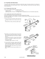
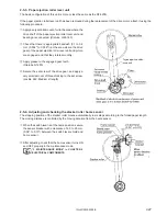
2-5-4. Adjusting and checking the stacker roller home sensor
The stopping position of the stacker roller moves automatically in six steps according to the folded paper length.
The moving distance is controlled by the moving duration from the home sensor.
q
When the switch lever is at the home position, secure
the sensor bracket with a clearance of 2.0 to 2.5 mm
(0.08" to 0.10") between the switch lever shield and
home sensor.
w
After adjusting, check that the home sensor turns ON
and OFF properly in the maintenance mode.
“3. MAINTENANCE MODE” in CHAPTER 2
ELECTRICAL COMPONENTS
See
See


