computer radio control system
EN
4.
4.
This function is great for timing retract gear servos.
Advice:
6.
Servo Reversing
Use this item to reverse the direction of a servo’s travel.
7.
Delay of positive/negative
This item allows you to delay the servo channel‘s travel time
between both end points. This can be defined for the positive and for
the negative value (each travel direction). For instance, the opening
of a landing gear can be slower than when it retracts.
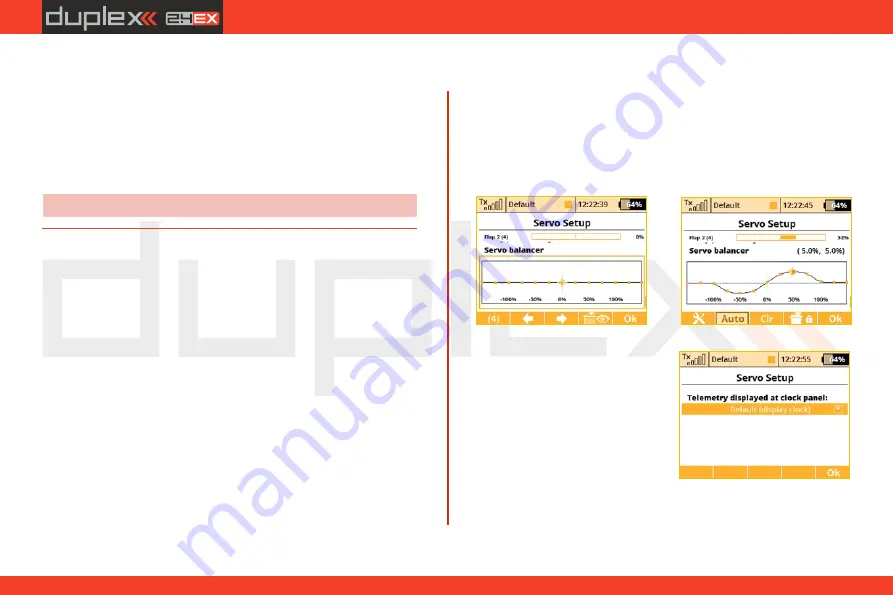
9.1.12 Servo balancer
The function of the servo balancer is designed for large models that
have control surfaces driven by mechanically linked servos. Since
each servo can be preset from the factory in a different way and
mounting servos into the model is not always accurate, it is now
possible to set servo travel algorithmically to ensure minimum
mechanical stress during the movement of the controls.
Thus it is possible to assign a separate curve to each output channel,
which is applied as the last operation before sending the deflections
to the model. Because it is applied last, the curve is ultimately
applied to trims, mixes, dual rates, etc., so that servos of the same
control surface always move together equally. The Servo balancer
can alter the curve of the servo by a maximum of ±10% with a
resolution of 0.1%.
1.
After you highlight the graph of the servo balancer, push the
"3D
button”.
This enables editing of the servo curve. Now, always one
control point is highlighted according to current servo deflection. If
the current servo position is -30%, the nearest highlighted control
2.
After pushing the
"F1 button”
when the servo balancer is
highlighted, the speed dial is
displayed. Here is where you can
select one telemetry parameter,
which will appear at location of the
digital clock on the top bar of the
screen. This way you can select, for
example, displaying the instant
current draw from the batteries,
which is very helpful when
balancing different servo travels.
point is located in -25%. It is then possible to move the point
upwards or downwards by turning the
„
3D button
”
to the right, or
respectively to the left. In
"Auto"
mode (the
„
F2 button
”
is
highlighted) simultaneous shifting of neighboring control points
occurs, so that the resulting curve is precisely smoothed. Then you
can select another control point by moving the servo control and
alter this point until the mutual mechanical stress of servos during
the movement is minimal.
(*depends on equipment)
64
Summary of Contents for Jeti DS-12
Page 2: ...computer radio control system EN...
Page 8: ...computer radio control system EN 8...
Page 51: ...computer radio control system EN 3 3 51...
Page 147: ...computer radio control system EN...
Page 148: ...computer radio control system EN...
Page 149: ...computer radio control system EN...
Page 150: ...computer radio control system EN...
Page 151: ...computer radio control system EN JETI model s r o Lomen 1530 742 58 P bor www jetimodel com...


