14
EN
2.00.390C - 1 User’s Manual
D Ü P E R T H A L S i c h e r h e i t s t e c h n i k G m b H & C o . K G
Frankenstr. 3
63791 Karlstein, Germany
Version March 2022
such damage would not be covered by the product warranty.
3.4 Setting the Pressure Difference
At a metering orifice, the suction line from the storage cabinet is equipped
with a pitot probe. The pressure difference it senses is measured by a dif
-
ferential pressure meter via the two transparent tubes routed to it. It rises
as the airflow through the suction-side extraction line on site increases.
With restricted or blocked airflow, the pressure difference sensed by the
probe drops. If it drops below the threshold set at the differential pressure
meter, a signal that an error condition has developed is sent into the en-
closure for further processing via the cable in the blue protective conduit.
For technical reasons (hysteresis), the threshold from which the monitor
cancels the error condition when the pressure difference rises again, is
a little higher than the threshold that triggers an error. Therefore, make
sure at all times that the settings for the pressure difference and the fan
speed of the air extraction system on site are matched to each other in
such a way that both an error is indicated when a restriction is detected,
and the error is canceled by the unit when the restriction is cleared. There
is no upper threshold for a maximum pressure difference.
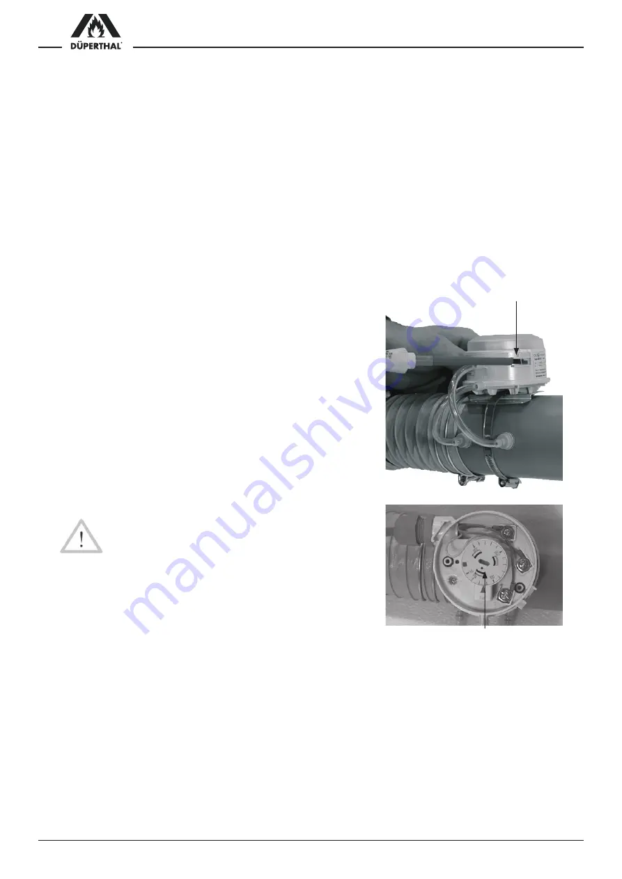
The value of the pressure difference threshold can be set at the
meter from 20 Pa to 300 Pa. This is done by simply removing the
transparent cover and using a screwdriver in the provided slot to
turn the selector. The factory-set default threshold of the pressure
difference is 70 Pa.
Setting the pressure difference threshold for monitoring the airflow
requires the following steps:
1. Connect the exhaust air monitoring unit properly to the ex-
traction system (outlet nipple) on site. Pay attention to the
installation of the sleeve of the differential pressure meter; it
has to tee into the line so the airflow passes through it in the
direction of the arrow.
2. Set the fan speed to the desired extraction airflow (see the
operator instructions of the fan system on site).
Caution
In a cabinet for flammable liquids, the extraction airflow
has to be sufficient to replace the interior volume of the
cabinet 10 times every hour.
3. Loosen the plastic cover of the differential pressure meter on
the suction hose (refer to the photograph to the right).
4. Using an appropriate screwdriver in the turning selector at the
center of the differential pressure meter, set the threshold to
make “Exhaust OK” appear on the screen (reduce pressure
difference). If no error is displayed on the screen at the start, the
pressure difference setting may first be increased until an error is
displayed, then slowly reduced again. The higher the pressure dif
-
ference threshold is set, the quicker / more sensitive the meter will
respond by throwing an error message.
5. Using appropriate means on site (e.g. by covering the exhaust outlet
with your hand), interrupt the extraction airflow temporarily.
6. If set correctly, the unit will trigger the audible alarm and display
the error message on the screen. After the airflow interruption is
cleared, the audible alarm should stop and the “Confirm error” mes-
sage should appear on the screen.
7. Reinstall the plastic cover on the differential pressure meter.
8. Confirm the error message on the screen by pressing the START/
SET key to re-open the dry contacts.
Latch clips to hold/remove
the plastic cover
Selector for setting the
pressure difference threshold
Summary of Contents for HNA-18 II ATEX F
Page 2: ......


