Front Panel Configuration
74
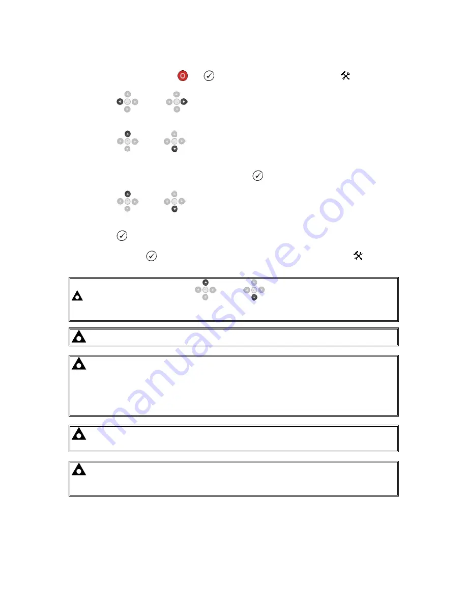
7.1 ACCESSING THE FRONT PANEL CONFIGURATION EDITOR
•
Press the
Stop/Reset Mode
and
(
) buttons together to enter the editor
mode.
•
Press the
(left) or
(right) navigation buttons to cycle through the front panel editor
in increments of 100.
•
Press the
(up) or
(down) navigation buttons to cycle through the front panel editor
in increments of 1.
•
When viewing the parameter to be edited, press the
(
) button and the value begins to flash.
•
Press the
(up) or
(down) navigation buttons to adjust the value to the required
setting.
•
Press the
(
) button the save the current value, the value ceases flashing.
•
Press and hold the
(
) button to save and exit the editor, the configuration icon
is
removed from the display.
NOTE: Pressing and holding the
(up) or
(down) navigation buttons gives an
auto-repeat functionality. Values can be changed quickly by holding the navigation buttons
for a prolonged period of time.
NOTE: The editor automatically exits after 5 minutes of inactivity to ensure security.
NOTE: The PIN number is not set by DSE when the module leaves the factory. If the
module has a PIN code set, this has been affected by your generator supplier who should be
contacted if you require the code. If the code has been ‘lost’ or ‘forgotten’, the module must
be returned to the DSE factory to have the module’s code removed. A charge is made for this
procedure.
NB - This procedure cannot be performed away from the DSE factory.
NOTE: The PIN number is automatically reset when the editor is exited (manually or
automatically) to ensure security.
NOTE: More comprehensive module configuration is possible via PC configuration
software. For further details of module configuration, refer to DSE Publication: 057-185
DSE71xx MKII Configuration Software Manual.
Summary of Contents for DSE7110 MKII
Page 34: ...Installation 34 4 2 1 DSE7110 MKII TYPICAL WIRING DIAGRAM 3 PHASE 4 WIRE ...
Page 35: ...Installation 35 4 2 2 DSE7120 MKII TYPICAL WIRING DIAGRAM 3 PHASE 4 WIRE ...
Page 36: ...Installation 36 4 3 ALTERNATE TOPOLOGY WIRING DIAGRAMS 4 3 1 GENERATOR ...
Page 37: ...Installation 37 4 3 2 MAINS DSE7120 MKII ONLY ...


