


G E T T I N G S T A R T E D
11
The following chart shows the status of the zone under certain conditions:
Loop Resistance ................................... Loop Status
5600
Ω
(contact closed) ........................ Secure
11200
Ω
(contact open) ......................... Violated
0
Ω
(shorted wire, loop shorted) ............ Fault
Infinite (broken wire, loop open) ........... Tamper
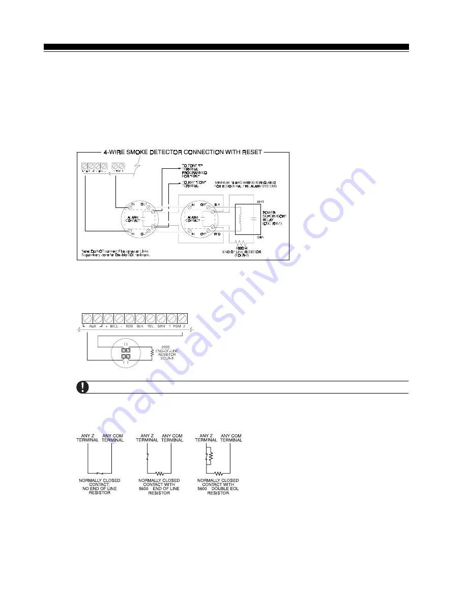
2.9.4
Fire Zone Wiring - 4 wire Smoke Detectors
All zones defined as Fire
(See
Section 5.1 “Zone Definitions”
) must be wired according to the following
diagram:
For a complete description of how fire zones operate,
Section 5.1 “Zone Definitions”
.
2.9.5
Fire Zone Wiring - 2 wire Smoke Detectors
If PGM2 has been programmed for 2 Wire Smoke Detector connection
the detectors must be wired according to the following diagram:
+
Ω
+
-
For a complete description of how fire zones operate,
Section 5.1 “Zone Definitions”
.
If PGM2 is programmed for 2 wire smoke support, Jumper J1 on the main board must be removed.
2.9.6
Keyswitch Zone Wiring
Zones may be programmed to be used as keyswitch arming zones and must be wired according to the
following diagrams:
Ω
Ω
For a complete description of how keyswitch zones operate,
see
Section 5.1 “Zone Definitions”
.