background image


DPC Touch User Manual 

3.


GETTING STARTED 

1.


Connect power supply to the controller to turn it on. Normal booting time is about 2 sec. If 
controller is not booted, the last booting step indicates the problem (e.g. 

Init SD Card…

 - 

missing or damaged SD card). 

2.


After first booting, calibration screen may appear. Follow instructions on the screen -press 
and hold the center of the cross for 1 sec for each position of the cross.  

ATTENTION

: if calibration is not correctly performed, the touch screen may become 

unresponsive. In this case turn off the controller, take out the SD card, access the SD card 
from your computer and delete the following file: 

SD:\system\setting\Setting_posi.dat


3.


Controller is started automatically in operating mode. If default job is selected it will start 
automatically.  

4.


Tap on the HOME button in order to access to the main menu screen. While not logged in, 
JOB MANAGER and SETTINGS are not accessible.  

5.


To log into the system tap on the LOGIN button. 

Default factory password is “0”.


4.


MAIN MENU 


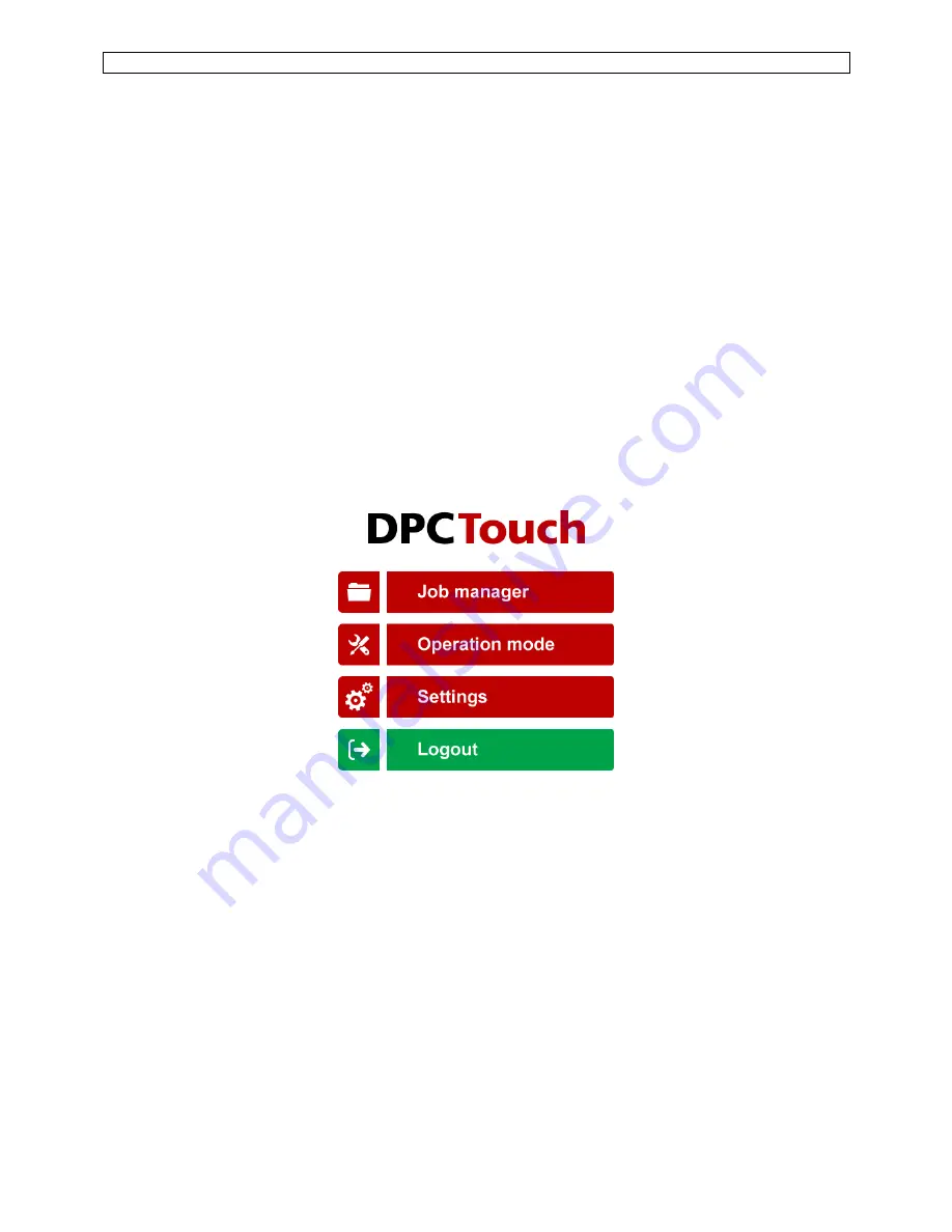
The main screen provides access to the main menu with four buttons: 

-


Job manager 

Provides access to the list of saved jobs and allows creation/modification jobs. This button is 
locked while user is logged out. 

-


Operation mode 

Provides access to the operating screen. 

-


Settings 

Provides access to the controller settings. This button is locked while the user is logged out. 

-


Login/Logout 

Allows logging into the system by entering the password to access 

Job manager

 and 

Settings

NOTE:


default factory password is “0”. If the password is lost, turn off the controller, take out the SD 

card, access the SD card from PC and delete the following file: 

SD:\system\setting\Setting_posi.dat


After rebooting, the controller will be reset to default factory settings. 

Summary of Contents for DPC Touch

Page 1: ... DPC Touch INSTRUCTIONS MANUAL ...

Page 2: ...ation has to be kept in a location known to all users Each operator has to read carefully this instructions manual before installing using and mending the product Be sure that the operator has understood usage recommendations and the meaning of signs put on the product Most accidents could be avoided respecting this Instructions Manual As a matter of fact they were created according to European la...

Page 3: ...GS 17 7 1 Operating 17 7 2 Encoders 19 7 3 Inputs 20 7 4 Outputs 21 7 5 Network 22 7 6 Other 22 8 OPERATING MODE 23 9 ELECTRICAL WIRING 24 9 1 Encoder s port wiring scheme 24 9 2 RS232 port wiring scheme 24 9 3 Inputs wiring scheme 25 9 4 Outputs wiring scheme 26 9 5 Connection of DOGA low voltage tools GX GY DO GA 27 9 6 Connection of DOGA Hybrid HDC and Current control SDC tools 28 9 7 Connectio...

Page 4: ...rd Removable SD card 8Gb 9 Total jobs memory 999 jobs with open structure 10 Total positions memory 999 jobs x 255 steps x 99 positions per fastening step max 999 positions in one job counter limit 11 Programming Automatic and manual programming of a Fastening step 12 Positioning accuracy 0 09 for angular encoders 0 5 mm for linear encoders 13 Positioning tolerance Adjustable for each position and...

Page 5: ...DPC Touch User Manual 6 2 HARDWARE 2 1 Dimensions and mounting interface Mounting plate with 4 x M3 screws is delivered with the controller as a standard accessory Weight of the controller 0 55 kg ...

Page 6: ...er for the wiring scheme Encoders port adaptor supplied only for controllers with serial numbers starting with SC Encoders port adaptor is used to connect standard DOGA positioning arms to DPC Touch ATTENTION Do not connect positioning arm directly to DPC Touch serial numbers starting with SC This may damage encoders Ethernet port I O port DB44 Encoders RS232 SD card 1 GX GY DO GA 2 GX GY DO GA Po...

Page 7: ...omatically 4 Tap on the HOME button in order to access to the main menu screen While not logged in JOB MANAGER and SETTINGS are not accessible 5 To log into the system tap on the LOGIN button Default factory password is 0 4 MAIN MENU The main screen provides access to the main menu with four buttons Job manager Provides access to the list of saved jobs and allows creation modification jobs This bu...

Page 8: ...b can t be loaded if it doesn t contain any steps Each job has its sequential number In order to change job number tap one more time on the selected job and then change its position in the list by using Up and Down buttons For information purposes number of steps and screws in a job is displayed in corresponding line in the list Home button provides access to the main menu screen Maximum number of...

Page 9: ...l Out this step is used to send an output signal s to manage automation equipment on work station e g activation of pneumatic valves lights etc Delay this step allows to maintain the current state of I O s for specified time e g a delay required between receiving an input signal and sending an output signal Message this step is used to display a graphical or text message on the operating screen du...

Page 10: ...hannels fields display saved values from analog encoders Current values are saved when Apply button is pressed or when Fastening OK signal is received Tolerance fields display tolerance values for analogue encoders to be applied for each encoder for the current position Tolerance values can be automatically detected by using Smart Tolerance detection feature please refer to corresponding chapter f...

Page 11: ...ion A Fastening step can be programmed manually or automatically 6 1 1 Manual programming of fastening step 0 Optional Use Smart tolerance detection feature refer to Smart tolerance detection below 1 Position the arm on the first screw Encoders monitoring fields are displaying the current position of the arm 2 Press APPLY button to save current position of the arm Saved values from encoders will b...

Page 12: ...g time will be registered automatically Min and Max tightening time limits are calculated automatically by using default values in operating settings Tightening time control is not used if limits are equal to 0 6 Repeat 1 5 for each position 7 Activate Non sequential mode if there is no need to keep strict tightening sequence NOTE in non sequential mode retightenings can t be managed 8 Press SAVE ...

Page 13: ...tton to quit programming without saving changes 6 3 Logical Output step creation While in Job modification screen tap on LOGICAL OUT button The Logical Out step creation screen will appear Select an available output and its type from the list of Outputs If an Output was assigned for a specific function in Output settings it is not available to be used as a logical signal There are two types of out...

Page 14: ...can be used but processing time will be longer Use provided converter utility to convert 24 bit images into 16 bit for better productivity Press SAVE button to save the step or CANCEL button to quit programming without saving changes Creating 16 bit bitmap images with Image Converter utility 1 Open Image converter utility 2 Select the directory where converted images are to be saved NOTE Image Con...

Page 15: ... on assembly status light 6 Message Text or Image message is shown on the screen to indicate parts to be picked 7 Logical Out One output signal continuous is sent to turn on pick to light indicator 1 8 Logical In One input signal active high is expected for picking verification by sensor 1 9 Logical Out Pick to light indicator 1 is turned off once picking is performed 10 Message Text or Image mess...

Page 16: ...ese inputs can function in binary logic or in direct logic one input per job ON OFF ON Default job number Default job is a job which is automatically started after booting of DPC Touch If default job number is set to 0 DPC Touch will not boot any jobs NOTE job selection via inputs has higher priority 0 999 1 Screen 2 of 4 Management of buttons in operating mode Skip button access without password ...

Page 17: ...is entered the tool will be instantly locked NOTE this parameter is used to avoid interruptions of fastening process when position is lost for short time due to vibrations 0 3000 50 Judging time ms Judging time is used if Fastening OK signal is delayed after the fall of Motor run signal 0 500 100 Screen 4 of 4 Management of NG tightenings Number of retightenings on a position Maximum number of att...

Page 18: ...t is possible to define two screw feeding positions or areas The tool can be enabled on the corresponding feeding position for easier screw picking Pick up position can be defined as a single point Corner 1 or as an area between Corner 1 and Corner 2 see below NOTE the real shape of pick up area is not rectangular and depends on the geometry of the arm To register location of a corresponding corne...

Page 19: ...e Previous Job Signal is used to select previous job in the job manager list Impulse Tool Alarm Fastening NG alarm signal from the tool to indicate that fastening operation wasn t successful Continuous or Impulse Set Origin Signal is used to set zero of encoders in operating mode Impulse D_Reverse Signal from tool to indicate that the tool is in reverse rotation mode DPC Touch will lock the tool i...

Page 20: ...ing D_Motor_Run input has to be connected Continuous D_TORQUE Signal is provided when Fastening OK signal is received from the tool D_Fastening_OK input has to be connected Impulse D_RESET Signal is provided when reset was made manually automatically or via I O Impulse Torque Select 1 8 Signals to select fastening presets on the tool in binary or direct logic see the table below Logic is selected ...

Page 21: ...esired sounds for Position Ok Alarm and Cycle complete signals Activate sounds to be used Date and time screen 3 of 4 Adjust current date and time The controller is equipped with internal battery to keep this data Language screen 3 of 4 Select language of the graphical interface Available languages in firmware v 0 2 8 English French German Spanish Password screen 4 of 4 Enter the new password and ...

Page 22: ...pped before reaching torque see settings Fastening NG tool alarm fastening NG alarm input signal is received from the tool System error operating system error reboot the controller I O error error of management of inputs and outputs check logical and assigned I O s Job complete NG job was interrupted or completed with missing screws 2015 12 25 12 05 Job selection button Previous job button Job man...

Page 23: ...24V Ch1 Ch3 8 24V Ch2 Ch4 9 Channel 4 9 2 RS232 port wiring scheme NOTE for the firmware upgrade mode pins 7 and 8 have to be short connected refer to the firmware upgrade manual Pin Function 1 5V power supply 2 Channel 1 3 Channel 2 4 GND Ch1 Ch3 5 GND Ch2 Ch4 6 Channel 3 7 24V Ch1 Ch3 8 24V Ch2 Ch4 9 Channel 4 Pin Function Port 1 Port 2 1 RX 2 2 RX 1 3 TX 1 4 5 GND 1 6 TX 2 7 8 9 GND 2 ...

Page 24: ...DPC Touch User Manual 25 9 3 Inputs wiring scheme ...

Page 25: ...DPC Touch User Manual 26 9 4 Outputs wiring scheme NOTE All outputs are optically isolated Max current capacity is 100mA per output Total of 500mA ...

Page 26: ...J45 I O port Signal RJ45 pin RJ45 pin Signal Torque Up input 2 2 Torque Up output Motor Run input 3 3 Motor Run output Driver Lock output 5 6 5 6 Driver Lock input 24V 4 4 24V Controllers XT 30D XS 38D XS 40D XS 35D XT 35D NOTE Select GX GY DO GA tool interface in DPC Touch operating settings The tool is locked by short connecting contacts 5 and 6 ATTENTION Use only straight RJ45 RJ45 cable not cr...

Page 27: ...l Output 1 Torque Select 1 1 1 Preset select 1 Output 2 Torque Select 2 2 2 Preset select 2 Output 3 Torque Select 3 3 3 Preset select 3 Output 4 Tool Disable 4 5 Driver Lock Input 8 D_Motor_Run 5 16 Motor Run Input 9 Tool Alarm 6 18 Alarm Input 10 D_Fastening_OK 7 25 Fastening OK IN_COM 8 22 0V DC OUT_COM 9 21 24V DC NOTE Select HDC SDC tool interface in DPC Touch operating settings Select PLC ex...

Page 28: ... Torque Select 4 4 4 Input 4 Preset select 3 Output 5 Tool Disable 4 5 Input 5 Driver Lock Input 1 D_Motor_Run 5 10 Output 1 Motor Run Input 2 Tool Alarm 6 11 Output 2 Alarm Input 3 D_Fastening_OK 7 12 Output 3 Fastening OK IN_COM 8 22 0V DC OUT_COM 9 21 24V DC NOTE All 8 inputs and 8 outputs of MDC controller are wired to DPC Touch controller These signals can be used for advanced functions manag...

Page 29: ...t Job 2 10 NO RE4 11 C 12 NC Output 1 5 Torque Select 1 1 7 Pset select 0 13 DI 1 DIGITAL INPUTS 14 Output 2 6 Torque Select 2 2 8 Pset select 1 15 DI 2 16 Output 3 7 Torque Select 3 3 9 Pset select 2 17 DI 3 18 Output 4 Tool Enable 4 25 Tool Enable 19 DI 4 20 OUT_COM 24V 9 23 24 Power supply 21 24V IN_COM GND 8 21 22 Ground 22 GND NOTE Select DC Tool interface in DPC Touch operating settings Eith...

Page 30: ...ool Input 8 D_Motor_Run 5 C Tool Running Trigger Input 9 Tool Alarm 6 K Cycle NOK Input 10 D_Fastening_OK 7 J Cycle OK IN_COM 8 V 0V DC OUT_COM 9 B 24V DC NOTE Select DC tool interface in DPC Touch operating settings In order to use 24V supply from Stanley controller short connect pins A and B In this case DPC Touch will be powered by Stanley controller Don t connect DPC Touch to external power in...

Page 31: ...1 Output 2 2 Output 3 3 Output 4 Tool Disable 4 4 Stop 5V in Input 8 D_Fastening_OK 5 6 Torque 24V out Input 9 D_Motor_Run 6 7 Lever 24V out Input 10 Tool Alarm 7 8 Error 24V out IN_COM 8 9 Com 0V DC OUT_COM 9 1 Com 0V DC NOTE Select DC tool interface in DPC Touch operating settings ATTENTION Cut the bridges 15 35 and 30 31 in the DB44 connector of the I O adaptor in order to disconnect 24V power ...

Page 32: ...t bit 0 Input Job select bit 1 Input Job select bit 2 Input Tool disable Output Fastening OK Output Fastening NG Output Motor run Input Job select bit 0 Input Job select bit 1 Input Job select bit 2 Input Tool disable Output Fastening OK Output Fastening NG Output Motor run Output 4 Torque select 1 Output 3 6 Torque select 2 Output 7 8 Torque select 3 Output 1 Tool disable Output 2 Logical out Loc...

Page 33: ...ut 8 Input 9 Input 10 Input 11 Input 12 In_COM In_COM Output 1 Output 2 Output 3 Output 4 Output 5 Output 6 Output 7 Output 8 Output 9 Output 10 Output 11 Output 12 Out_COM Out_COM 24V 24V 24V GND GND GND 5 6 7 8 1 2 3 4 9 1 2 3 4 5 6 12 13 14 15 16 17 21 22 25 7 8 9 10 11 18 19 20 23 24 Push button 1 Push button 2 Proximity sensor Light 1 Light 2 Light 3 Relay DB25 DB44 DB9 DPC Touch max 100mA ma...

Page 34: ...Torque Select 2 Output 3 18 3 Torque Select 3 Output 4 19 25 4 Tool Disable Output 5 20 7 Tool Enable Output 6 21 8 D_Run Output 7 22 9 D_Torque Output 8 23 10 Alarm Output 9 24 11 Job OK Output 10 25 18 Logical Out Output 11 26 19 Logical Out Output 12 27 20 Logical Out 28 OUT_COM 29 23 24 9 In Com 24V 30 24V 31 32 33 34 0V 35 36 37 38 39 40 41 42 43 44 ATTENTION By default the controller provide...

Page 35: ...real time monitoring Outputs are optically isolated Image message is overlapped with operating screen Press on the screen where Image button is situated top middle in order to initialize the screen Use recommended pictures format 16 bit bitmap To convert images into 16 bit format use image converter utility Image message is not displayed on the screen Check image size and format Images have to be ...

Page 36: ...Doc 60290 12 17 ...

Reviews: