DPC Touch User Manual
19
7.2
Encoders
Encoder’s
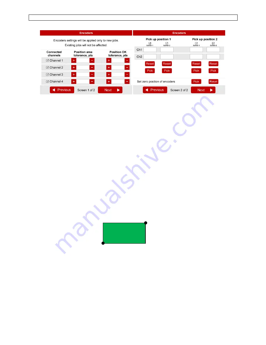
activation and tolerance settings (screen 1 of 2)
Activate or deactivate corresponding encoders by selecting check boxes accordingly.
Enter default tolerance values for the approaching Area and for OK zone where tool is enabled.
Default tolerance values are applied automatically during Fastening step creation. It is possible to
modify tolerances manually for each individual position during creation of a fastening step.
If default tolerances are changed they will be applied only to new jobs, existing jobs will not be
affected.
See more information about approaching Area and OK zone tolerances in Fastening step creation
chapter.
Pick up position 1 and 2 (screen 2 of 2)
It is possible to define two screw feeding positions or areas. The tool can be enabled on the
corresponding feeding position for easier screw picking.
Pick up position can be defined as a single point (Corner 1) or as an area between Corner 1 and
Corner 2 (see below).
NOTE:
the real shape of pick-up area is not rectangular and depends on the geometry of the arm.
To register location of a corresponding corner, position the arm and press
Pick
button.
Setting zero point of encoders (screen 2 of 2)
Encoders’ reference point can be defined by using this function. Definition of the reference point is
useful when encoders have to be replaces after failure or when repeatability of position of the
work
piece can’t be assured.
The reference point can be defined by using
Pick
button or reset by using
Reset
button. The
reference point can also be defined by using external input signal in Operating mode.
Pick up area
Corner 1
Corner 2


