User Manual
FlexxPump 125 Power Supply (24V DC)
SCHMIERSYSTEME
D I R E C T L U B R I C A T I O N S Y S T E M S
D L S
Page 1: ...User Manual FlexxPump 125 Power Supply 24V DC SCHMIERSYSTEME D I R E C T L U B R I C A T I O N S Y S T E M S D L S ...
Page 2: ...ing those of photomechanical reproduction duplication and distribution by means of special processes e g data processing data carriers and data networks even in part and or in extracts are reserved by DLS Schmiersysteme GmbH The content and technical specifications are subject to change without notice I II Imprint of the manufacturer distribution and service Adress DLS Schmiersysteme GmbH Gewerber...
Page 3: ...or information 07 2 Safety 08 2 1 EC EU Directive 08 2 2 Hazards 08 2 3 Staff 08 2 4 Reasonably predictable misuse 08 2 5 Usage for the intended purpose 09 2 6 Warranty and Liabilty 09 2 7 General safety instructions 10 3 Description of function 11 3 1 General information 11 3 2 Nameplate and designation 12 3 3 Scope of delivery 12 3 4 Technical data 13 4 Transport and storage 14 4 1 Packaging 14 ...
Page 4: ... PUL 43 6 3 12 FIL Menu 44 6 4 Error codes 45 7 Input and output signals Time Control 47 7 1 Pin assignment Time control 47 7 2 Output signals and LCD messages Time control 47 7 3 Output signals at PIN 4 Time control 48 8 Input and output signals External control PLC 50 8 1 Pin assignment External control PLC 50 8 2 Input signals External control PLC 51 8 2 1 Control signal 2 seconds 52 8 2 2 Cont...
Page 5: ...C A T I O N S Y S T E M S D L S 10 Released accessories 70 10 1 Lubricants 72 10 2 Tube lengths 72 11 Appendix 73 11 1 Dimension sheet and installation dimension 73 11 2 EC EU Declaration of conformity 74 11 3 Spare parts 75 11 4 Flowchart Pulse Control Mode PUL 76 Chapter Content Page ...
Page 6: ...maintenance of the FlexxPump 125 There fore keep these instructions in a suitable place ideally in an easily accessible place in the surrounding area of the FlexxPump 125 Inform your colleagues who work in the local area of the machine about safety instruc tions so that nobody gets hurt This manual was written in German all other language versions are translations of this manual 1 1 Signal words T...
Page 7: ... important information 1 3 Structure of the safety instructions The safety instructions in this user manual are structured according to the following system CAUTION The text explains the consequences of disregarding the refe rence The text shows what to do as an instruction 1 4 Symbols for information The following information symbols are used in the text and instructions in this manual Requests y...
Page 8: ...prohibited until it has been clearly established that the machine complies with the provisions of the applicable Directive An EC EU declaration of conformity for the FlexxPump 125 can be found in the appen dix chapter I II 2 2 Hazards In order to avoid danger to the user or damage to the machine on which the FlexxPump 125 is used the FlexxPump 125 may only be used for its intended purpose chapter ...
Page 9: ... accident prevention and environmen tal protection must be observed Work and activities with and on the FlexxPump 125 are only permitted with appropri ate authorisation chapter 2 3 All other uses than the aforementioned intended usage or the disregard of one of the above points shall be deemed improper usage In this case no liability and or warranty is assumed 2 6 Warranty and Liabilty If the foll...
Page 10: ...Loose or overloaded screw connections can cause damage to the FlexxPump 125 Mount and check all screw connections with the permissible torques specified for this purpose Use a calibrated torque wrench WARNING Lubricants are flammable In case of fire do not use a water jet to extinguish the fire In case of fire use only suitable extinguishing agents such as powder foam and carbon dioxide Observe th...
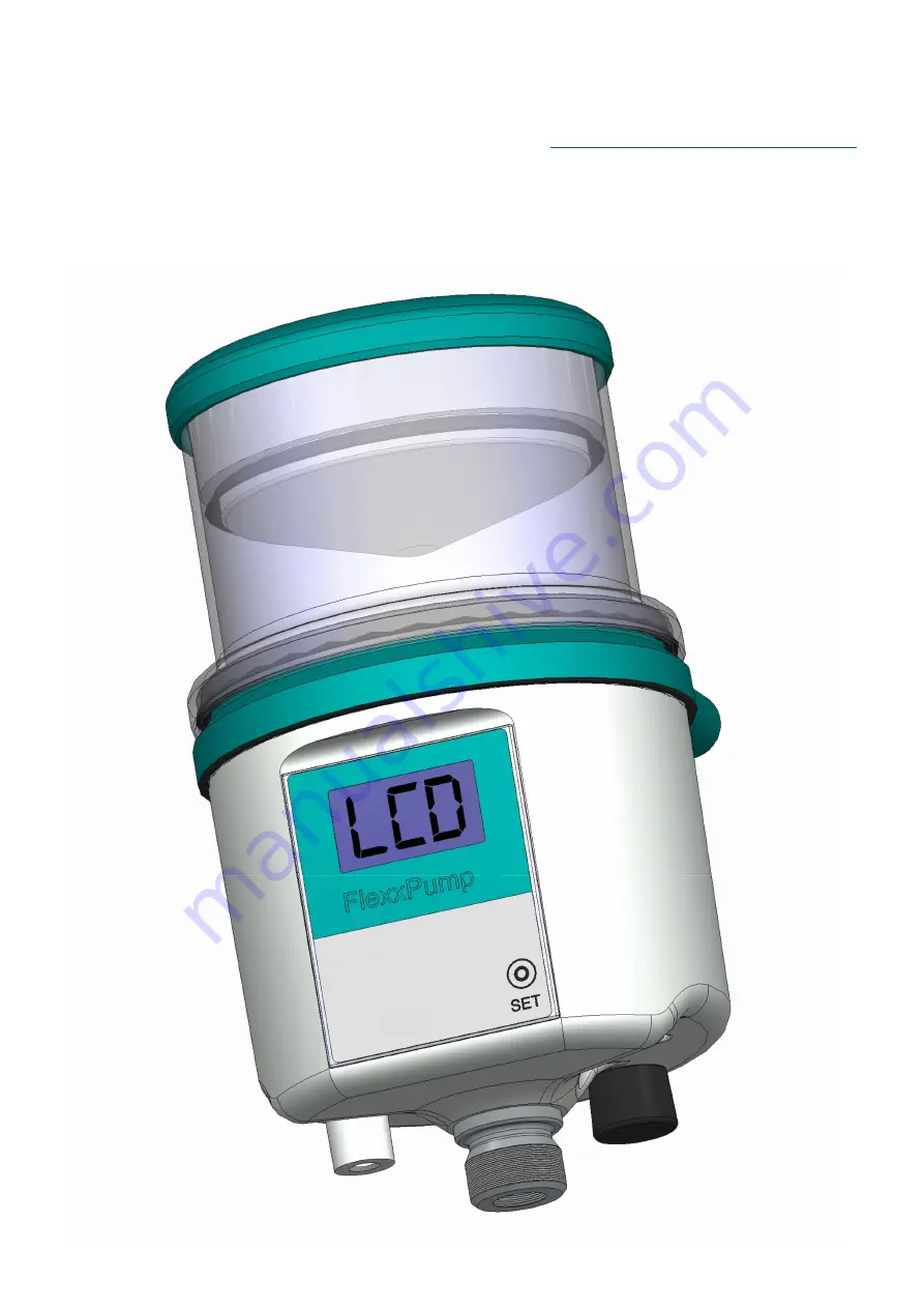
Page 11: ... 1 Overview FlexxPump 125 2 1 5 6 3 0 The FlexxPump 125 is designed as an extremely compact double piston pump with grease or oil as the lubricant The two pistons run force controlled and counter rotating They are united on one outlet The outlet is secured by an integrated non return valve Approx 0 15 cm of lubricant is pumped during each dispensing operation multiple dispensers can be set one aft...
Page 12: ...he location of the nameplate and serial number 3 3 Scope of delivery The FlexxPump 125 is available in several different versions They differ in the number of accessories supplied All versions of the FlexxPump 125 are prefilled with a neutral food grade H1 lubricant approx 3 cm which can be mixed with the lubricants approved by DLS Schmiersys teme GmbH to simplify the initial commissioning The man...
Page 13: ... housing PA 6 6 GF30 POM Material outlet stainless steel Operating temperature 15 60 C Lubricant and hydraulics Volume cartridge 125 or 250 cm Lubricant characteristics grease until NLGI class 2 Number of outlets 1 Hydraulic connection directly or via PA tube Number of lubrication points up to 8 in conjunction with aluminum progressi ve distributor max pressure 50 10 15 bar Grease delivery per str...
Page 14: ...ging materials at the designated disposal points in compliance with the relevant national and company regulations After receiving the FlexxPump 125 check the delivery note for completeness and correctness Any missing parts or damage must be reported immediately to the forwarding agent the insurance company or DLS Schmiersysteme GmbH in writing 4 2 Transport NOTICE Hard shocks e g due to falling or...
Page 15: ...nd can transport dirt and foreign matter into the FlexxPump 125 or the lubricant Do not use pressurised air Make sure that there is no coarse dirt in the mounting area 2 Remove protective cap from top of the FlexxPump 125 Remove the yellow protective cap from the top of the lubricant inlet of the Flexx Pump 125 Make sure that no dirt water or foreign bodies enters the lubricant inlet 5 2 Assembly ...
Page 16: ...xxPump 125 using a suitable connecting cable Depending on the application both connection cables with straight or angled sockets can be used Please refer to chapter 7 1 or chapter 8 1 for the condition of the connection cable LCD DANGER Defective or faulty electrical connections or unauthorized live components can lead to serious injuries or even death Have all electrical connection work carried o...
Page 17: ...tention to cleanliness when carrying out the work It is imperative that dirt and foreign bodies do not enter the cartridge 6 Mounting the lubricant cartridge Place the full lubricant cartridge on the FlexxPump 125 Turn the lubricant cartridge clockwise onto the FlexxPump 125 The end position is reached after two full rotations when the label of the lubricant cartridge is aligned with the front lab...
Page 18: ...ut the FlexxPump 125 into operation switch on the FlexxPump 125 Only if you switch the FlexxPump 125 on it delivers lubricant to the lubrication point according to the settings The detailed description for powering on can be found in chapter 6 3 3 5 Execute FIL function Execute the FIL function The detailed description can be found in chapter 6 3 12 FlexxPump 125 performs a certain number of strok...
Page 19: ...e integrated into a control system PLC In the Pulse Control Mode PUL this controller can be used to command and control the FlexxPump 125 see Chap 7 and Chap 8 How to change to the operation mode PUL is described in detail in Chap 6 3 7 A dispensing cycle consists of at least one 1 donation stroke and can consist of a maximum of ten 10 donations strokes Up to ten 10 donations strokes are made in d...
Page 20: ...ths for a full 125 ml lubricant cartridge provided that the FlexxPump 125 is permanently switched on and no special dispensations have been made Within approx 6 hours the FlexxPump 125 will deliver one donation per stroke 0 16 cm Verify that the default settings are appropriate for your application and that the lubri cation point is supplied with the correct amount of lubricant per time unit If th...
Page 21: ...roperly mounted and installed and then switched on Installation is very simple and described in detail in chapter 5 2 switching on is described in chapter 6 3 3 If you order a special version of FlexxPump 125 from the factory the information contained in the supplement is authoritative for you 6 2 2 Default setting operating mode Empty Time Mode Et 6 2 3 Default setting operating mode Pulse Contro...
Page 22: ... ON The individual submenus are presented described and explained in detail in chapters 6 3 4 to 6 3 12 The symbolic representations used below are described as follows Symbol Description Note Detail chapter LCD Anzeige The LCD displays information both during operation and for pro gramming purposes 6 3 1 Sequence arrow The black sequence arrow indicates the unchangeable basic structure of the men...
Page 23: ... naviga tion For details see chapter 6 3 3 The INF Menu can only be accessed from the OFF mode FlexxPump 125 is switched off The INF Menu provides you with an informative overview of the current FlexxPump 125 settings For details see chapter 6 3 4 6 3 5 and 6 3 6 The SET Menu can only be accessed from the OFF mode FlexxPump 125 is swit ched off The SET Menu allows you to make changes to the operat...
Page 24: ... 125 is switched on The PRO Menu allows you to make changes to the FlexxPump 125 settings and thus to its dispensing behavior For details see chapter 6 3 9 6 3 10 and 6 3 11 The FIL Menu is only accessible from the ON mode FlexxPump 125 is switched on The FIL menu allows you to manually trigger a fixed number of donations to the Flexx Pump 125 For details see chapter 6 3 12 ...
Page 25: ...ore the error occurs Error with the Flexx Pump 125 6 4 The yellow LED only lights up if the activation and programming key has touched the action surfa ce activation and programming key detected Activation and pro gramming key detected by Flexx Pump 125 6 3 The green LED lights up during a dispensing process for approx 10 18 seconds FlexxPump 125 dispen ses lubricant 6 3 The green LED lights up wh...
Page 26: ...n 15 sec 8 2 Errors E1 Error E1 Empty cartridge no cartridge detected 6 4 E2 Error E2 Overload 6 4 E3 Error E3 Undervoltage 6 4 E4 Error E4 fatal error 6 4 Sub Menu INF INF Menu 6 3 4 6 3 5 6 3 6 n01 Firmware version of the FlexxPump 125 h06 Currently set value of the pause time h c01 Currently set value of the number of cycles c 6 Currenty set value of the emptying time Et PUL Currently set opera...
Page 27: ... Currently set operating mode Pulse Control Mode no changeable variable FIL FIL Menu 6 3 12 01 50 During the manually triggered active FIL command the LCD displays the approximate back pressure in bar In addition the green LED lights up Clr If the process is aborted during the FIL command Clr appears first Additional character on the LCD Displayed when the cartridge is empty and the cartridge and ...
Page 28: ...the FlexxPump 125 The activation and programming key is permanently held magnetically in the hole on the underside Simply pull it out 2 Guide the activation and programming key to the action area SET Place the activation and programming key on the action area on the front of the FlexxPump 125 As soon as the activation and program ming key on the action area SET has been detected by FlexxPump 125 t...
Page 29: ... The hole on the bottom of the FlexxPump 125 does not necessarily have to be used to store the activation and programming key If you want to protect FlexxPump 125 against unintentional modification or manipulation you can also store the activation and programming key in another location Please note however that in the event of faults or changes to be made no changes or actions can be carried out o...
Page 30: ...pense lubricant according to the set values Insert the activation and programming key into the hole provided on the underside of the FlexxPump 125 FlexxPump 125 is ON the green LED flashes every 30 seconds Hold the activation and programming key on the action surface The yellow LED lights up Leave the activation and programming key on the action area until OFF is displayed in the LCD Remove the ac...
Page 31: ...25 set value of the cartridge size Remove the activation and programming key from the housing of the FlexxPump 125 and place it on the action area Hold the activation and programming key on the action area The yellow LED lights up Leave the activation and programming key on the action area until INF is displayed in the LCD Remove the activation and programming key from the action area as long as I...
Page 32: ...the lubricant cartridge Remove the activation and programming key from the bottom of FlexxPump 125 and place it on the action area Hold the activation and programming key on the action surface The yellow LED lights up Leave the activation and programming key on the action area until INF is displayed in the LCD Remove the activation and programming key from the action area as long as INF is display...
Page 33: ... and programming key from the housing of the FlexxPump 125 and place it on the action area Hold the activation and programming key on the action area The yellow LED lights up Leave the activation and programming key on the action area until INF is displayed in the LCD Remove the activation and programming key from the action area as long as INF is displayed in the LCD The yellow LED disappears the...
Page 34: ...t can be adjusted after selecting the operating mode in the PRO menu see Chapter 6 3 9 6 3 10 or 6 3 11 The cartridge size can be set between 125ml and 250ml h Operating mode Hour Mode Et Operating mode Emtpy Time Mode PUL Operating mode Pulse Control Mode 125 250 Changeable parameter of the cartridge size FlexxPump 125 is switched off OFF Remove the activation and programming key from the bottom ...
Page 35: ...CD now displays the currently set value of the cartridge size Now you have the possibility to change the value of the used cartridge size Changing the used cartridge size If you want to change the cartridge size move the activation and programming key back to the action area The yellow LED lights up and the LCD displays the currently unselected cartridge size The yellow LED lights up as long as th...
Page 36: ...s no fault or error at FlexxPump 125 Remove the activation and programming key from the bottom of FlexxPump 125 and place it on the action area Hold the activation and programming key on the action surface The yellow LED lights up Leave the activation and programming key on the action area until RUN is display ed in the LCD Remove the activation and programming key from the action area as long as ...
Page 37: ...s exactly as many strokes in succession after triggering the RUN function as were set in the PRO menu in the variable c If you are in the operating mode Empty Time Et the FlexxPump 125 performs only one 1 stroke after triggering the RUN function The RUN Menu can only be reached from the ON mode FlexxPump 125 switched on When you have entered the RUN Menu you will return to the ON mode ...
Page 38: ...en sing time h There is no fault or error at FlexxPump 125 In the PRO menu the first step is to set the pause time h and afterwards the number of cycles c direct access to the number of cycles c is not possible Remove the activation and programming key from the housing of FlexxPump 125 and place it on the action area Hold the activation and programming key on the action surface Leave the activatio...
Page 39: ...ring the PRO Menu The LCD as well as the green LED flashes twice and the pause time h is displayed in the LCD The submenu now automatically takes you to the values of the number of cycles The LCD now displays the currently set value of the number of cycles c cis Now you have the possibility to change the values of the number of cycles c Changing the value of the number of cycles c If you want to c...
Page 40: ... 125 will immediately start with the calculated waiting time until the next pause Observe the back pressure values displayed on the LCD if they are of interest to you During the pause process the green LED lights up in addition the counterpressure for the stroke is displayed in the LCD The parameters that can be set for the pause time h and the number of cycles c and their respective permissible v...
Page 41: ...e action area Hold the activation and programming key on the action surface Leave the activation and programming key on the action area until PRO is displayed in the LCD Remove the activation and programming key from the action area as long as PRO is displayed in the LCD The LCD flashes together with the green LED twice The LCD first displays the cur rently set value of the emptying time Et Etis N...
Page 42: ...ering the PRO Menu The LCD as well as the green LED flashes twice and the emptying time Et is display ed in the LCD Insert the activation and programming key into the hole provided on the underside of the FlexxPump 125 The PRO Menu can only be reached from the ON mode FlexxPump 125 switched on When you enter the PRO Menu you will return to the ON mode If you have made changes to the values of the ...
Page 43: ...ol Mode PUL The PRO menu allows you to change the settings of the FlexxPump 125 s dispensing behavior If you are in Pulse Control Mode PUL no settings can be changed The FlexxPump 125 is integrated into a control system PLC and commanded and control led by the PLC see Chap 7 and Chap 8 PUL for pulse mode is displayed as a purely informative matter in the LCD ...
Page 44: ...isplayed in the LCD Remove the acti vation and programming key from the action area The yellow LED disappears The LCD flashes together with the green LED twice The FlexxPump 125 starts donating The green LED lights up during each donation If you do not want to cancel the process Insert the activation and programming key into the hole provided on the underside of the FlexxPump 125 FlexxPump 125 dis...
Page 45: ...tridge Error Cartridge not recognized or corrently not mounted Place a new cartridge on FlexxPump 125 see chapter 9 2 No confirmation of the error necessary it is automatically cleared after the remedial action Error E1 Cartridge Symbol empty Place a new cartridge on FlexxPump 125 see chapter 9 2 No confirmation of the error necessary it is automatically cleared after the remedial action Error E2 ...
Page 46: ... 125 is commanded and controlled by an external controller PLC in the event of an error the PLC will be informed about the error E1 E4 by different error messages as output signals via PIN 4 of the electrical interface of the FlexxPump 125 Chap 8 3 LCD Name Description Remedy Error E4 Fatal error Disassemble the Flexx Pump 125 and return it to the manufacturer together with the lubricant cartridge...
Page 47: ... tapped for further processing e g indicator light or external control The maximum permissible output current must not exceed Imax 20mA No inductive load e g relay may be connected PIN Assignment PIN Assignment Colour 1 24 V DC brown 2 unallocated white 3 Ground blue 4 output signal black Type M12x1 female connector 4 pin A coded 1 4 3 2 LCD Description Output signal PIN 4 Detail OFF switched off ...
Page 48: ...lso allows status control from a distance 7 3 Output signals at PIN 4 Time control Output signal high level 24 V at PIN 4 U 24V 0V t PIN 4 Description A permanently and continuously present high level 24 V at PIN 4 means that the FlexxPump 125 is ready for operation and there is no error The FlexxPump 125 will operate according to the settings made and will accordingly convey lubricant from the ca...
Page 49: ... does not pump lubricant Find remedial actions in chapter 9 2 8 Input and output signals External control PLC To command the FlexxPump 125 via an external controller PLC it is necessary to switch the FlexxPump 125 to Pulse Control Mode PUL in the SET menu chapter 6 3 7 In Pulse Control Mode the FlexxPump 125 operates as a pulse controlled lubrication system only if unalterable input signals high l...
Page 50: ...age The settings made are not lost After reapplying the supply voltage the FlexxPump 125 checks itself automatically but only operates after receiving an input signal from the PLC To operate the FlexxPump 125 via an external controller PLC in Pulse Control Mo de a program corresponding to the communication protocol must be created in the PLC A basic flowchart for the command of the FlexxPump 125 c...
Page 51: ...ls which must be transmitted from the PLC to the FlexxPump 125 via PIN 2 of the electrical M12x1 interface as high level 24 V DC The control signals must be generated as high level 24 V by the external controller PLC over certain times with a tolerance of 0 1 seconds The FlexxPump 125 in Pulse Control Mode PUL only processes the control signals listed in the table up to a maximum length of 14 seco...
Page 52: ...pecified pause time this control signal can be repeated or another control signal can be sent The FlexxPump 125 reacts only in a certain operating state to control signals at PIN 2 The operating states are output by the FlexxPump 125 via PIN 4 as a high low level and must be tapped and processed accordingly in the PLC U 24V 0V t PIN 2 U 24V 0V t PIN 4 2s 3s Tp 22s 7 ML 17 s 3s o E o E Tp Pause tim...
Page 53: ...tor run ML the FlexxPump 125 sends a low level output signal to the external controller PLC as confirmation for the duration of the motor run ML The motor running time ML depends on various conditions including the coun terpressure present or built up in the hydraulic system and the temperature With the FlexxPump 125 the motor running time ML is 7 17 seconds ML 7 17 seconds While the engine is run...
Page 54: ...out automatically one after the other After a certain pause time this control signal can be repeated or another control signal can be sent The FlexxPump 125 reacts only in a certain operating state to control signals at PIN 2 The operating states are output by the FlexxPump 125 via PIN 4 as high low levels and must be tapped and processed accordingly in the PLC U 24V 0V t PIN 2 U 24V 0V t PIN 4 12...
Page 55: ...on of the motor run ML The motor running time ML depends on various conditions including the coun terpressure present or built up in the hydraulic system and the temperature With the FlexxPump 125 the motor running time ML is 7 17 seconds ML 7 17 seconds While the engine is running the green LED in the LCD lights up in addition a nu merical value of 1 50 is displayed in the LCD which indicates the...
Page 56: ...s is used to acknowledge error messages of errors E2 and E3 It is the only control signal that the FlexxPump 125 can process when a low level output signal is sent Irrespective of the basic possibility of remote acknowledgement of an error it is essential to identify and eliminate the cause when an error message is present U 24V 0V t PIN 2 U 24V 0V t PIN 4 10s 3s o E o E 14s ...
Page 57: ...l PLC At the end of the control signal the integrated microelectronics of the FlexxPump 125 will automatically check itself If this internal check is successful the output signal at the FlexxPump 125 chan ges from a low level to a high level error E2 or E3 is thus acknowledged and the FlexxPump 125 is ready for operation again CLR is briefly displayed in the LCD then PUL again If this internal che...
Page 58: ...ration high permanent Chap 8 PUL flashing Receiving control signal high permanent Chap 8 01 50 Dispensing process low 10 18 Seconds Chap 8 E1 Cartridge empty 0 5Hz square wave signal perma nent Chap 8 3 1 E1 No Cartridge low permanent Chap 8 3 2 E2 Overload low permanent Chap 8 3 3 E3 Undervoltage low permanent Chap 8 3 4 E4 Critical error low permanent Chap 8 3 5 8 3 Output signals LCD messages E...
Page 59: ...mitted to the external control PLC in time For this purpose a separate unique output signal is provided which can be easily and reliably detected by the external control PLC U 24V 0V t PIN 4 1s 1s 1s 1s 1s 1s 1s Description The FlexxPump 125 is properly connected to an external controller via the electrical interface and connected to the power supply The Pulse Control Mode PUL is activated on the ...
Page 60: ...125 is initially the 0 5Hz square wave signal empty state signal 0 24 V Z1 indicates the time of removal of the empty cartridge The output signal of the FlexxPump 125 now changes from a 0 5Hz square wave signal to a permanent low signal 0V Z2 indicates the time for screwing on a new full cartridge The output signal of the FlexxPump 125 now changes from a permanent low signal 0V to a permanent high...
Page 61: ...nected to the power supply The Pulse Control Mode PUL is activated on the FlexxPump 125 E1 is displayed in the LCD and the red LED lights up Error E1 No cartridge must and cannot be acknowledged Remedial action is descri bed in chapter 9 2 Error E1 No cartridge interrupts current dispensing operations on the FlexxPump 125 The FlexxPump 125 sends a permanent low level 0 V as output signal to PIN 4 ...
Page 62: ...een successfully controlled by the external control PLC immediately before the occurrence of error E2 and has attempted to perform a dispensing operation The Pulse Control Mode PUL is activated on the FlexxPump 125 E2 is displayed in the LCD and the red LED lights up When the maximum permissible pressure is reached during or after a donation the FlexxPump 125 sends a permanent output signal as low...
Page 63: ... an external controller via the electrical interface and connected to the power supply The Pulse Control Mode PUL is activated on the FlexxPump 125 E3 is displayed in the LCD and the red LED lights up If the supply voltage is too low the FlexxPump 125 sends a permanent output signal as low level 0 V to PIN 4 for external control PLC Error E3 undervoltage must be acknowledged with the control signa...
Page 64: ... interface and connected to the power supply The Pulse Control Mode PUL is activated on the FlexxPump 125 E4 is displayed in the LCD and the red LED lights up In an internal diagnosis the critical exception error E4 has been detected The error E4 cannot be corrected by you on site and cannot be acknowledged by you on the FlexxPump 125 Remove the FlexxPump 125 with the lubricant cartridge screwed o...
Page 65: ...operational safety regulations Do not deactivate any protective device without authorization 9 1 Maintenance schedule The following maintenance schedule must be observed for the FlexxPump 125 Maintenance Commis sioning After 500 hours or after 3 months Every year If required Cleaning x x x x Visual check x x x x Cartridge change x x x Depending on operating conditions and lubricant consumption Dep...
Page 66: ...heck that the FlexxPump 125 is turned on Carry out a Quick Check test run using the RUN command chapter 6 3 8 9 1 1 Visual check Check the entire lubrication system FlexxPump 125 and any connected accessories including tubes and distributors for external damage e g loose or loosened tubes by a thorough and conscientious visual inspection Check the condition of the lubrication point for correct sup...
Page 67: ... flashes every 5 seconds NOTICE A used lubricant cartridge must not be replaced on the Flexx Pump 125 as the integrated stroke counter of the FlexxPump 125 is automatically reset by the cartridge sensor after a car tridge has been removed Only use full lubricant cartridges NOTICE Only use original lubricant cartridges with lubricant approved by the manufacturer Observe the maximum shelf life of lu...
Page 68: ... Pay attention to cleanliness during the work Make sure that dirt and foreign bodies do not get into the lubricant inlet If neces sary carry out cleaning work beforehand chapter 9 1 2 2 Mounting the new lubricant cartridge Place the full lubricant cartridge on the FlexxPump 125 Turn the lubricant cartridge clockwise onto the FlexxPump 125 The end position is reached after 2 full rotations when the...
Page 69: ...exxPump 125 automatically returns to the last active mode ON or OFF befo re the completion of this work If the empty state of the cartridge Error E1 was reached during a dispensing cycle it is automatically interrupted and continued automatically after completion of the work explained above 9 3 Disposal When disposing the FlexxPump 125 empty or opened cartridges observe the rele vant national regu...
Page 70: ...ation Application 000 101 101 cartridge FlexxPump 125 125 cm F01 adhesive grease for open gears 000 102 101 cartridge FlexxPump 125 125 cm F02 H1 approval 000 103 101 cartridge FlexxPump 125 125 cm F03 universal grease 000 104 101 cartridge FlexxPump 125 125 cm F04 multi purpose grease 000 114 101 cartridge FlexxPump 125 125cm GB0 high performance universal grease 000 101 102 cartridge FlexxPump 1...
Page 71: ...B R I C A T I O N S Y S T E M S D L S 134 200 000 bracket for Flexx Pump 125 universal bracket for easy mounting at backwards structure on request Splitter 2 to 4 outlets multipoint lubri cation on request Aluminium progressi ve distributor 2 to 10 outlets multipoint lubri cation ...
Page 72: ...not mount the FlexxPump 125 directly on or at the lubri cation point contact the manufacturer to verify your application The influence of tem perature the grease used the hoses and accessories used does not allow a general statement to be made about the possible hose length on the FlexxPump 125 10 2 Lubricants Only use lubricants approved by the manufacturer DLS Schmiersysteme GmbH in the original...
Page 73: ...it nicht ausdrücklich zugestanden Alle Rechte vorbehalten Rohstoff Raw material Gewicht Weigth DLS Art Nr Part No Benennung Designation Sachnummer Part No Blatt Sheet Zul Abw f Maße ohne Toleranzang General tolerances von of Norm Appr Gepr Check Datum Date Name Name Bearb Drawn Ausg Issue Änderung Modification Datum Date Name Name Menge Quantity Maßstab Scale Dateiname Filename Maße in mm Dimensio...
Page 74: ...revision 0 FlexxPump 125 24V User Manual 74 EN SCHMIERSYSTEME D I R E C T L U B R I C A T I O N S Y S T E M S D L S 11 2 EC EU Declaration of conformity ...
Page 75: ... 10 11 Sekunden PIN 4 3 Sekunden high FlexxPump demontieren und an Hersteller einschicken nein Steuersignal nicht erfolgrich erkannt Start ja ja ja Start nein ja n e i n nein The adjacent figure illustrates the basic program flow chart for the control signal 2 seconds chapter 8 2 1 which triggers a stroke with 0 16cm lubricant on the Flexx Pump 125 in Pulse Control Mode as well as possible errors ...
Page 76: ...iersysteme GmbH Gewerbering 5 D 82140 Olching Tel 49 0 89 650 69 0 Fax 49 0 89 650 69 29 mail DLS Schmiersysteme de www DLS Schmiersysteme de SCHMIERSYSTEME D I R E C T L U B R I C A T I O N S Y S T E M S D L S ...