background image

Instruction Manual  

SAFELINE VARIO Diagnostics 

11

2 Rack-Diagnostics

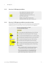
The application is read out of the 
central module. (Fig. 2-4)

 
Fig. 2-4


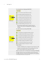
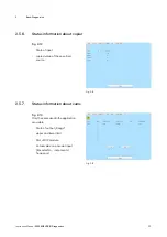
The status of the hardware specified in the application is displayed. . (Fig. 2-5)


The main menu is divided into 4 areas:

 In 

Section  1

 the diagnostic buttons are located. These open different diagnostic functions or start  


or close a diagnostic. The functionality of the menu items is described more detailed in the chapter  


“Diagnostics buttons“.

 In 

Section  2

 the real rack is simulated. Not used slots are displayed empty. More information to  


this section in chapter “Read out Rack information”.

 In

 Section  3 

is located in the right corner of the window. The modules selected by the operater  from  


area 2 are shown here enlarged. For more information see chapter „Modul Diagnostics“.

 In 

Section  4

 status information selected modules related to area 3 are displayed. More information  


in chapter “Status information“.

Fig. 2-5

Summary of Contents for SAFELINE VARIO

Page 1: ...SAFELINE VARIO Diagnosis Instruction Manual dina de 0 1 2 3 4...

Page 2: ...in particular to the reproduction distribution and translation of this documentation or parts thereof as well as the storage and processing of this content using electronic data processing systems Th...

Page 3: ...0 2 5 3 Status information about timers 22 2 5 4 Status information about counters 23 2 5 5 Status information about safety mats 23 2 5 6 Status information about copier 24 2 5 7 Status information ab...

Page 4: ...d displayed by the software The use of graphic elements makes it very easy to detect errors and to identify the operational states of the SL VARIO modules and errors can be quickly and effectively eli...

Page 5: ...ith the USB interface 3Open application if necessary enter password for authorization to use the application Fig 1 1 Fig 1 1 3Adjust interface in the menu transmission interface Fig 1 2 see designer m...

Page 6: ...eterminalsontheinputsandoutputsorsafetycircuitschangecolordependingonwhethertheterminal is connected ornotconnected orifanerrorisdetectedinthisterminal In case an entire symbol turns orange a fault is...

Page 7: ...setpoint Lower value actual value Bei zweikanaliger berwachung durch Initiatoren werden jeweils die Werte beider Kan le angezeigt Operating mode MUTE and the function Muting without sensor monitoring...

Page 8: ...erminal red short circuit or wire break Analog input Upper values parameterized limits Upper value current analog value Terminal gray analog value is outside the configured limits Terminal green analo...

Page 9: ...Black set parameter Blue current analog values Analog Input Comparator Black set parameter Blue current analog values Analog Output Black set parameter Blue current analog values ANA terminal changes...

Page 10: ...reproduced The operating conditions of the respective modules and their details such as axis states operating modes safety circuits etc can be detected 2 1 Starting the Rack Diagnostics 3Open designe...

Page 11: ...stic The functionality of the menu items is described more detailed in the chapter Diagnostics buttons In Section 2 the real rack is simulated Not used slots are displayed empty More information to th...

Page 12: ...es the user to the error diagnostics window In this window all errors are listed in detail This window is described in the chapter Error Diagnostics HISTORY After each SL VARIO programming information...

Page 13: ...the corresponding module yellow it indi cates a plausibility error however does not necessarily lead to a SLOK OFF state Error information of the modules can be accessed by clicking on the red slot nu...

Page 14: ...igital input that has been parameterized as a reset input Analog inputs If the inputs of ZMV are used as analog inputs the following applies Green if voltage current within the configured range Grey i...

Page 15: ...ed monitoring with sin cos TTL HTL or resolver measuring systems 1 2 3 4 1 if f parameterized standstill frequency at first monitoring 1 if f parameterized standstill frequency at first monitoring 2 i...

Page 16: ...1 2 3 4 1 if f parameterized standstill frequency at I9 I10 1 if f parameterized standstill frequency at I9 I10 2 if f parameterized standstill frequency at I11 I12 2 if f parameterized standstill fre...

Page 17: ...rcuit 8 is met ZH1 ZH2 Conditions for two hand control 1 2 are met MODS1 MODS2 an output on the Operating mode selector MODE SLCT is set System OK SL VARIO is working properly IO1 IO2 CLK IO1 IO2 and...

Page 18: ...wing additional area appears if the application contains the function speed monitoring Fig 2 6 Fig 2 6 SMx Configured speed monitoring Selection with a left click The corresponding field is blue Initi...

Page 19: ...latch function of the speed monitoring in conjunction with the designer provides good diagnostic capabilities to determine the causes of shutdowns In case of a shutdown the state of the speed monitori...

Page 20: ...le corresponding to about 1 6 of the reduced speed Error position comparison The increments of the tracks Sin Cos or A B are monitored through 2 channels at the position monitoring If the position dev...

Page 21: ...error Checksum error To delete acknowledge these error messages the icon RTSK has to be wired 2 5 3 Status information about timers Timers with 4 inputs Fig 2 8 x the respective timer is configured a...

Page 22: ...n about safety mats Fig 2 11 State of output Actual value at input terminal Fixed values where the safety mats switch Latched values Incaseofashutdownthestateofthe analoginputislatchedandbuffered andc...

Page 23: ...opier Fig 2 12 State of input copied value of the specified source Fig 2 12 2 5 7 Status information about cams Fig 2 13 Onlythe camsused inthe application arevisible State of output Range upper and l...

Page 24: ...G1 Drive 1 is within the limit G2 Drive 2 is within the limit Latch Synchronous operation was is not guaranteed Actual values Latch values Latch Werte In case of a shutdown on the output the actual st...

Page 25: ...luation Minimum value Maximal value Actual value at the analog terminal Latch values Latch Werte In case of a shutdown the state of the analog input is latched and buffered and can be displayed in thi...

Page 26: ...thestateofthe analoginputislatchedandbuffered andcanbedisplayedinthismask as longasthepowerisnotturnedoffand thelatchfunctionisnotacknowledged To delete acknowledge these lat ched values the icon RTSK...

Page 27: ...ing modules Status information DSV Slot Slot number In the left pane the following states are represented The boxes are checked if the conditions are met SK1 SK4 Conditions for safety circuit 1 safety...

Page 28: ...g mode Istwert current actual value SIN COS encoder type If the operating mode MT is selected the observed target value for each speed module is defined as infinite In the display field for the corres...

Page 29: ...monitoring is latched or buffered and can be displayed in the designer as long as the power is not turned off and the latch function is not acknowledged Press the button following menu is displayed s...

Page 30: ...ble corresponding to about 1 6 of the reduced speed Error position comparison The increments of the tracks Sin Cos or A B are monitored through 2 channels at the position monitoring If the position de...

Page 31: ...n FBV With the buttons IN OUT 1 and IN OUT 2 the section of fieldbus inputs and outputs FBI O1 8 or FBI O9 16 are selected The bits of FBIx correspond to the FB inputs FBIx 1 FBIx 8 in the logic diagr...

Page 32: ...two hand control are met IO1 IO2 CLK IO1 and IO2 are configured as clock outputs IO3 IO4 CLK IO3 and IO4 are configured as clock outputs 2 9 Status information about In Output Module IOV Status inform...

Page 33: ...ion about network module NIV Status information NIV Slot Slot number Network address Specifies the address of the NIV module whose data are presented here The box will be checked if the following cond...

Page 34: ...ndicate an incorrect but not leading to SLOK OFF state of SL VARIO SLOK OFF always requires a restart of the central module Any detected errors will cause the slot number field of the affected module...

Page 35: ...llowing buttons can be selected with a left click Display current errors If this button is activated the latest error information on SL VARIO are being constantly read and displayed Display saved erro...

Page 36: ...ed or stored errors are read In section 3 following information is available on Checksums Firmware version of the connected device Application specific data such as machine name author date Spezielle...

Page 37: ...re arranged according to the time of programming In the index 1 are the last transmitted data 4 1 Read out History Dieser Button ffnet einen Notizblock in dem Sie Projektnotizen nach Datum und Uhrzeit...

Page 38: ...ion Manual SAFELINE VARIO Diagnostics 38 4 History 4 2 Delete History 3 To delete the history press the button Delete History Fig 4 3 If SL VARIO was provided with a password a password will be asked...

Reviews: