Instruction Manual
SAFELINE VARIO Diagnostics
6
1 Online-Diagnostics
1.2.
Display of the symbols in the online diagnostics
The states are displayed differently according to the configured symbol. (Fig. 1-6)
Fig.
1-6
This way at the speed monitoring both the parameterized target and the actual values are displayed.
The current value is always displayed at the time and counters. Setpoints and actual values are
also visible on all analog elements in the symbol.
The terminals on the inputs and outputs or safety circuits change color depending on whether the terminal
is connected or not connected or if an error is detected in this terminal.
In case an entire symbol turns orange, a fault is indicated, but does not necessarily
lead to SLOK OFF.
Errors can be dedected more specific by applying the rack diagnostics.
The color of the connecting lines indicates the high / low state of this connection.
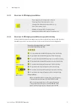
Symbol
Display
Description
Input
(also for safety-related
functions)
Terminal grey
= Input off
Terminal green
= Input on
Terminal orange
= error at the input,
e.g. clocked input is activated static
Output
Terminal grey
= output off
Terminal green
= output on


