Instruction Manual
SAFELINE VARIO Diagnostics
14
2 Rack-Diagnostics
2.4.
Module Diagnostics
By left clicking on one of the modules in the rack (section 2), this specific module will appear in
section 3. The terminals and the LEDs of this module are shown here enlarged. The states are
constantly updated.
2.4.1.
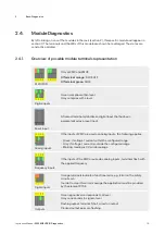
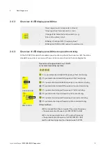
Overview of possible module terminals representation
A1 24V/DC
Only at ZMV and ZMVK
A1 Terminal orange:
SLOK OFF
A1 Terminal green:
SLOK
Digital inputs
Green complies with H-level
Grey complies with L-level
Reset input
A framed terminal symbolizes a digital input that has been
parameterized as a reset input.
Analog inputs
If the inputs of ZMV are used as analog inputs, the following applies:
• Green: if voltage / current within the configured range
• Grey: if voltage / current is outside the configured range
• Blinking: reading is 0V, wire breakage
Frequency inputs
If the inputs of the ZMV are used as analog inputs, terminals flash with
the applied frequency.
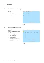
Digital inputs
Orange terminals indicate a functional error, e.g. Error on the safety
circuit sein.
In order to clear this error message the application must be provided
by the element RTSK.
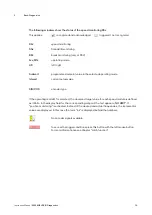
Outputs
Green signal level corresponds to H-level
Gray corresponds to signal L-level
Flashing output terminal: Short circuit on output
Clocked output pairs are flashing.


