Instruction Manual
SAFELINE VARIO Diagnostics
15
2 Rack-Diagnostics
2.4.2.
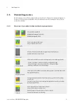
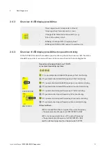
Overview of LED display possibilities
•
Green signal level corresponds to H-level
•
Gray signal level corresponds to L-level
•
Orange LEDs indicate a functional error, e.g.
Error on the safety circuit.
•
Blinking of an input LED: Frequency input
•
Blinking (with 2Hz) at LED output: transistor error
2.4.3.
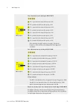
Overview of LED display possibilities to speed monitoring
At the SL VARIO modules that enable speed monitoring shows the mean row LED the status
standstill, speed ok or over speed. These states are also shown in the rack diagnostics.
DSV/DRV/SIV
ZMV/ZMVK
Speed monitoring with sin/cos, TTL/HTL
or resolver measuring systems
1 2 3 4
1
if f<= parameterized standstill frequency at first monitoring
1
if f> parameterized standstill frequency at first monitoring
2
if f<= parameterized standstill frequency at second monitoring
2
if f> parameterized standstill frequency at second monitoring
3
if f<= parameterized speed frequency at first monitoring
3
if f> parameterized speed frequency at first monitoring
4
if f<= parameterized speed frequency at second monitoring
4
if f> parameterized speed frequency at second monitoring
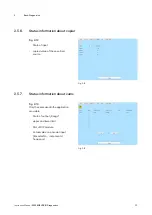
After shutdown
• LED for standstill switches on again if the actual frequency
< the parameterized frequency (at ZMV/ZMVK <4Hz).
• LED for over speed switches on if the actual frequency
< the parameterized frequency (at ZMV/ZMVK <4Hz)
and the acknowledgement has happened with RTDS.


