background image

MCQ-PRO RFID Reader 

— Installation and Tuning Manual                                              Version 1.00                         

Page 27 of 89 

2.


Click the icon 

 to add this device to favorites. 

Alternatively, you may as well double-click the device or right-click the device and 
choose “Add to Favorite Devices”. 


If you are already connected to a device plugged into your computer’s serial or 
USB ports, it will not appear during device discovery until you disconnect from 
it. This is a normal behavior. 


If  a  firewall  is  active  on  your  computer,  you  should  authorize  incoming  UDP 
packets on port 4002 to allow device discovery. 

With Windows Firewall, this can be performed on control panel’s  “Exceptions” 
tab. 


To ensure discovered TCP/IP devices can be connected to, Dialoc ID  MCQ-Pro 
automatically  pings  them.  If  “[Unreachable]”  is  displayed  next  to  a  device  in 
“Device Discovery” panel, this means that pinging this device has failed and you 
may  not  be  able  to  connect  to  it  using  its  Ethernet  interface.  This  is  usually 
because device and computer network addresses do not match. Try changing the 
TCP/IP configuration of your computer or of the device. 


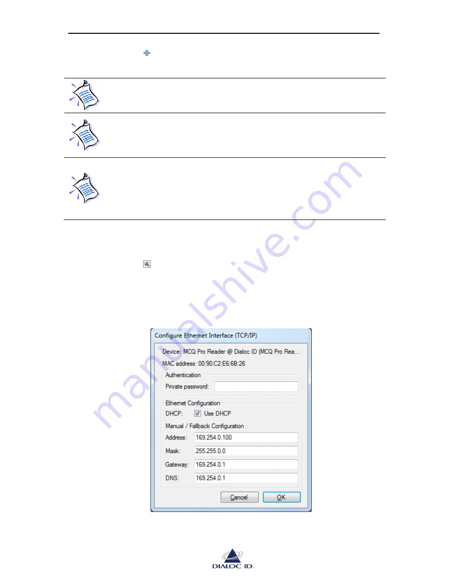
To change the TCP/IP configuration of a discovered Ethernet device that is unreachable: 

1.


Select the unreachable device. 

2.


Click the icon 

 to configure its Ethernet interface.  

Alternatively, you may as well right-click the device and choose “Configure Ethernet 
Interface (TCP/IP)”. 


Figure 16: Configure Ethernet Interface (TCP/IP) 


Summary of Contents for MCQ-PRO

Page 1: ...User Manual Version 1 00...

Page 2: ...e for errors contained herein or for incidental or consequential damages in connection with the furnishing performance or use of this material Dialoc ID assumes no responsibility for the use or reliab...

Page 3: ...out 24 4 1 5 Switching workspace to full screen 24 5 Managing your RFID devices 25 5 1 How to Manage your Favorite Devices 25 5 1 1 Adding a Favorite Device Using Device Discovery 25 5 1 2 Manually Ad...

Page 4: ...4 4 Custom tab 68 9 5 I Code ePC 69 9 5 1 Parameters tab 69 9 5 2 Memory tab 70 9 5 3 Destruction tab 71 9 6 I Code UID 72 9 6 1 Parameters Tab 72 9 6 2 Memory Tab 73 9 6 3 Destruction Tab 73 9 7 I Co...

Page 5: ...MCQ PRO RFID Reader Installation and Tuning Manual Version 1 00 Page 5 of 89 12 2 2 Capture and Display settings 89...

Page 6: ...formation and the like described herein at any time Therefore DIALOC ID assumes no liability and is not responsible for customer applications or product or software that include DIALOC ID products DIA...

Page 7: ...to persons or property denial of service or loss of privacy Copyright DIALOC ID 2012 MS DOS and Windows are registered trademarks of Microsoft Corporation Printed in the Netherlands DIALOC ID Daltons...

Page 8: ...Conventions Symbol Meaning CAUTION A note that advises users that a specific action could result in loss of data or damage the hardware WARNING A note that advises users that a specific action may res...

Page 9: ...9 Quality Issues DIALOC ID implements stringent quality controls at all stages of its manufacturing process However should you find a defect with this product please notify us using the RMA form on ou...

Page 10: ...CQ Pro reader It also permits you to easily setup the reader test it and perform RFID reading and writing operations This document provides a step by step guide for the following procedures Installing...

Page 11: ...SE Windows ME legacy operating system supported but not recommended Microsoft NET Framework version 2 0 or later 128 megabytes MB of RAM 256 MB recommended 300 MB of free hard disk space This includes...

Page 12: ...n click Next again if you agree Figure 2 Select Installation Folder window 2 Select the folder where MCQ Pro software will be installed then click Next Figure 3 Confirm Installation window 3 Click Nex...

Page 13: ...DIALOC ID MCQ Pro connect your RFID reader to the serial USB port of the PC or to your TCP IP network Connect one or more antennas to the reader Once the reader is ready run DIALOC ID MCQ Pro program...

Page 14: ...set up DIALOC ID MCQ Pro to perform basic tasks such as configuring your RFID device and read write operations If the DIALOC ID MCQ Pro Wizard did not automatically open click on the Wizard icon in t...

Page 15: ...Serial USB Ethernet this device is available on Prefer Ethernet interface when available as it is the fastest communication interface You can refresh the Discovered devices at any time by clicking on...

Page 16: ...ommunication settings check I want to configure device s system interfaces or services To perform read write operations and send tag specific commands check I want to read or write tags on then select...

Page 17: ...ion and Tuning Manual Version 1 00 Page 17 of 89 Figure 8 Wizard Summary page Check Wizard settings and click on Finish to confirm DIALOC ID MCQ Pro software will automatically open panels you need an...

Page 18: ...3 2 1 Reading UID of ISO 15693 Tags This section shows how to read asynchronously the UID of ISO 15693 tags see section 8 for more information about asynchronous read To start reading operation with...

Page 19: ...rted Figure 10 DIALOC ID MCQ Pro reading ISO 15693 tags 4 Click button in the toolbar when you are finished reading You may turn the radio field off as well clicking button 3 2 2 Reading or Writing IS...

Page 20: ...to write and enter its data as hexadecimal bytes You can pad bytes with whitespaces if you wish but this is not mandatory Figure 12 Single Block Operations The length in bytes of a single block depen...

Page 21: ...h Add select tag type ISO15693 set to power slider to the power for this antenna 3000mW and select the both Emitter and Receiver for the channel the antenna is on Repeat the Add procedure for all ante...

Page 22: ...al or lateral panels float Minimize lateral panels as vertical tabs Reset panel placement to the default layout The figure below illustrates different ways to position the panels Figure 13 DIALOC ID M...

Page 23: ...osition indicated release the mouse button To move an undocked panel without snapping it into place press CTRL while dragging it 4 1 2 Minimizing panels Lateral panels which can be docked on left and...

Page 24: ...urn the workspace to the original panel layout by choosing Restore Default Panel Layout in the View menu 4 1 5 Switching workspace to full screen You can switch the workspace to full screen by clickin...

Page 25: ...es panel click on the icon in the toolbar or select Favorite Devices in the Device menu Figure 14 Favorite Devices panel Registering a new Favorite Device can either be done manually or using Device D...

Page 26: ...k Choose Discover All Devices to discover both kind of devices 3 Devices are listed Point out the mouse cursor to the device to get its information A same device can be displayed one or more times dep...

Page 27: ...rmed on control panel s Exceptions tab To ensure discovered TCP IP devices can be connected to Dialoc ID MCQ Pro automatically pings them If Unreachable is displayed next to a device in Device Discove...

Page 28: ...tes 1 Open Favorite Devices panel by clicking on the icon in the toolbar or by choosing Favorite Devices in the Device menu 2 Click the icon to add a new favorite device This will open the Device Edit...

Page 29: ...formation Product Name DIALOC ID RFID device product name Description and Location give custom information set for this device They can be set in System Configuration panel see section 6 1 for more in...

Page 30: ...ion about a channel Hardware and Firmware gives hardware and firmware version Supports Tags indicates tags supported by the channel Power indicates minimum and maximum power supported by the channel O...

Page 31: ...ID device System firmware which manages protocols and interfaces for communication with the host Radio firmware which manages RFID operations System Firmware Upgrade To upgrade system firmware 1 Open...

Page 32: ...ystem firmware upgrade completed Radio Firmware Upgrade To upgrade radio firmware 1 Open Favorite Devices panel by clicking on the icon in the toolbar or by choosing Favorite Devices in the Device men...

Page 33: ...lt radio configuration is loaded from internal non volatile memory NVRAM when device is powered on Saving Radio Configuration to NVRAM To make your radio configuration persistent you must save it to N...

Page 34: ...ry settings 1 Open Favorite Devices panel by clicking on the icon in the toolbar or by choosing Favorite Devices in the Device menu 2 Connect to the device that you want to restore the radio configura...

Page 35: ...e and click Save to save the configuration file To load device configuration from disk 1 Open Favorite Devices panel by clicking on the icon in the toolbar or by choosing Favorite Devices in the Devic...

Page 36: ...6 of 89 Figure 27 Load Device Configuration dialog 4 Click Select button to choose location of configuration file 5 Check device settings to load and click Load to save the configuration file Settings...

Page 37: ...vice menu 6 1 1 General Tab You can configure general system settings on General tab Figure 28 System Configuration panel General tab Device Information You can view and modify device s description lo...

Page 38: ...password no settings can be changed If logged into the device using private password then changes are permitted DIALOC ID MCQ Pro requires to log into protected devices using private password Default...

Page 39: ...re displayed in History list See Designer s Guide for more information about supported commands 6 2 Communication Interfaces Configuration Open Interface Configuration panel by clicking on the icon in...

Page 40: ...anual Version 1 00 Page 40 of 89 Figure 31 Interface Configuration panel USB tab 6 2 3 Ethernet Tab You configure device s Ethernet communication interface and view its status on Ethernet tab Figure 3...

Page 41: ...eriodically on the network via the Ethernet communication interface and is used for discovering the device and monitoring its proper operation You configure the heartbeat period on this tab Figure 33...

Page 42: ...in the toolbar or by choosing RF Channels Configuration in the Radio menu 7 1 1 Default RF configuration Default RF configuration represents the channel configuration that will be used for any subsequ...

Page 43: ...n 8 or sending commands to tags see section 9 To turn RF on or off click or button in the toolbar CAUTION Make sure antennas are connected to channels you use before turning the radio field on otherwi...

Page 44: ...nds sent to tags it allows before the multiplexer switches to the next pattern or the first if this pattern is the last If both switch conditions are defined the first condition met will trigger the s...

Page 45: ...s this limit b Maximum rounds number of Wake up commands sent to the tags during which this pattern remains active When this maximum is reached the multiplexer switches to the next pattern or the firs...

Page 46: ...on 9 for more information 4 Click button in the toolbar CAUTION Make sure an antenna is connected to channels you use before turning the radio field on otherwise it may severely damage the device 5 Cl...

Page 47: ...equests DIALOC ID MCQ Pro to play system bell each time a tag is detected Radio buffer polling period changes the period used by DIALOC ID MCQ Pro when polling events from device s radio This is usefu...

Page 48: ...detected in RF Reference Tags Add adds tags in reference list You can add tags manually or from tag event panels Tags are defined by data UID returned during default read Use Tag Data field below refe...

Page 49: ...time a tag frame is detected in radio field New Tag event occurs the first time a tag is detected in radio field Tag In and Tag Out events come in pair and occur respectively when a tag enters or lea...

Page 50: ...econds that should elapse without having detected the tag in the radio field before triggering a Tag Out event 8 2 4 Read Mode Read mode defines the radio device behavior during default read Before st...

Page 51: ...s when reading asynchronously that the radio should automatically stop reading after o In default RF read mode one single round not valid with C210 C220 tags o In multiplexer read mode having scan all...

Page 52: ...nd to select all copy some or clear all rows from the event list Each read event has the following fields Data contains data received from the tag Type contains tag type Ch n contains read count of th...

Page 53: ...Tag Events panel is similar to Tag Read Events panel please refer to section 8 3 1 for more information 8 3 3 Tag In Tag Out Events You can open Tag In Out Events panel from Radio Default Read menu T...

Page 54: ...ault Read menu Raw Events panel shows all events having occurred on device s radio It permits in particular to watch No Read events Figure 44 Raw Events panel As hundreds of radio events can occur by...

Page 55: ...ed by channel or globally the event frame rate and elapsed time since reading started If several radio events are enabled see 8 2 3 for more information you can change the event type used for statisti...

Page 56: ...ecifications according to the tag types Before sending any command to tags you should define default radio configuration and turn the radio field on see section 7 1 1 for more information 9 1 C210 Ope...

Page 57: ...nly specifies if only lockable memory should be read during asynchronous read process even if tags are in long reply mode Sensitivity defines reader sensitivity when attempting to detect a C220 in the...

Page 58: ...ick Enable Disable to enable disable EAS state of all C220 tags in the RF field Tags must be locked for this operation to function properly To change EAS state of unlocked tags use memory writing oper...

Page 59: ...uld be fast 16 ms or normal 33 ms during asynchronous read process lockable Short reply Specifies if the reply size should be short only lockable memory data is sent or long both non lockable and lock...

Page 60: ...block 32 LSBits and its second memory block 32 MSBits The following options are available Memory Only Read memory blocks only Memory blocks are reported sequentially UID Only Read the UID from tag s f...

Page 61: ...tag is affected to a distinct time slot and displayed in the list The number of time slots defined in I Code parameters see section 9 1 1 is used while performing tag selection If there were not enoug...

Page 62: ...n radio field To perform selected halt choose one or several tags from Tag Selection list and click Selected Halt You can quiet I Code tags permanently by setting their quiet bit with selected write c...

Page 63: ...and Commands menu 9 4 1 Parameters Tab Figure 52 ISO 15693 panel Parameters tab Uplink Device to Tag Device communicates with tags using ASK Amplitude Shift Keying or OOK On Off Keying You can choose...

Page 64: ...ping Vicc ISO 15693 tags memory is organized into fixed size blocks Up to 256 blocks can be addressed and each block can consist of up to 32 bytes 256 bits This provides a maximum memory size of 8 kil...

Page 65: ...tags will be reported if the threshold is set to 0 Quiet tags once read requests tag to stay quiet once read Advanced Set write option flag specifies if write option flag should be set for all subseq...

Page 66: ...your ISO 15693 tags and configure device s radio as explained in section 9 2 1 Application Family Identifier AFI To set AFI of some tags choose an addressing mode enter AFI as a hexadecimal byte in AF...

Page 67: ...9 4 3 Memory tab Figure 54 ISO 15693 panel Memory tab Memory operations are dependant on the memory organization supported by your ISO 15693 tags and require that you configure device s radio as expla...

Page 68: ...To perform a multiple block operation place ISO 15693 tags in radio field choose an addressing mode enter the first block decimal and the number of blocks to use decimal enter optionally the data to...

Page 69: ...you to change the number of time slots used during default read Default Read To set a mask select Mask length field and enter it in Mask field During default read only tags whose ePC matches this mask...

Page 70: ...Tuning Manual Version 1 00 Page 70 of 89 9 5 2 Memory tab Figure 57 I Code ePC panel Memory tab Write All Operation To write ePC of all tags currently in radio field enter the code as 12 hexadecimal b...

Page 71: ...ePC panel Destruction tab Destroy Code Setting To write destroy code of all tags currently in radio field enter the code as 3 hexadecimal bytes in Code field and click Set Code Destroy Tag Setting To...

Page 72: ...change the number of time slots used during default read Default Read To set a mask select the length in Mask length field and enter it in Mask field During default read only tags whose ePC matches th...

Page 73: ...eration To write ePC of all tags currently in radio field enter the code as 12 hexadecimal bytes in ePC field and click Write All 9 6 3 Destruction Tab Figure 61 I Code UID panel Destruction tab Destr...

Page 74: ...Reader Installation and Tuning Manual Version 1 00 Page 74 of 89 Destroy Tag Setting To destroy tag currently in radio field enter its ePC UID in ePC UID fields and its destroy code in Code field and...

Page 75: ...be read To read tags UID check Read UID The UID and then memory blocks will be reported sequentially To select which part of the memory should be read enter the first block in First block decimal fie...

Page 76: ...to enable disable EAS state Click Lock to prevent any future state change of EAS Click Check to get current state of EAS 9 8 I Code SLI L S C370 L S Open I Code SLI L S panel by choosing I Code SLI L...

Page 77: ...mory blocks are reported sequentially Check Fast Mode to specify whether to use page inventory tag command B0h or fast page inventory tag command B1h See I Code SLI L S specifications for more informa...

Page 78: ...ion uses the term of Setting password instead of Logging in with password Do not confuse this with Writing password below Password Configuration To write a password select its type in Password type li...

Page 79: ...re using those commands you may have to authenticate with EAS password as explained in section 9 8 2 To read current EAS ID click Read To write current EAS ID enter its value as two hexadecimal bytes...

Page 80: ...eration must be performed in selected or addressed mode Memory Protection Before using those commands you must authenticate with memory read or memory write password as explained in section 9 8 2 I Co...

Page 81: ...section 9 8 2 and click Enable privacy When in privacy mode tag will not accept further commands unless privacy password is logged in again Destroy To destroy a tag you must authenticate with destroy...

Page 82: ...MCQ PRO RFID Reader Installation and Tuning Manual Version 1 00 Page 82 of 89 You can write ePCs of I Code SLI L S tags in Memory tab of I Code ePC panel see section 0...

Page 83: ...adio menu Figure 69 IO Sets Configuration panel You can watch on this panel IO Set temperature and inputs status You can as well control outputs state by clicking on their LEDs Inputs are green when a...

Page 84: ...is a sequence of bytes composed of several optional and customizable ASCII fields For all radio events but No Read event the frame has the following canonical format Header Timestamp Suffix Radio ID...

Page 85: ...r Installation and Tuning Manual Version 1 00 Page 85 of 89 You can configure format of the message frame sent on serial port when a tag is read on Message Format tab Figure 70 Standalone Mode panel M...

Page 86: ...gure the period used and the message to send in Watchdog Interframe Delay If the device in standalone mode is connected to a slow legacy system it may be necessary to slow down frame rate to avoid flo...

Page 87: ...ing to connect to a TCP IP device DIALOC ID MCQ Pro tries to ping it If pinging timeouts connecting will not be attempted You can define in Ping timeout field the time in milliseconds to wait before a...

Page 88: ...nnels configuration see section 7 for more information 2 Click button in the toolbar to turn the radio field on CAUTION Make sure an antenna is connected to channels you use before turning the radio f...

Page 89: ...ure data in a CSV file using the drop down menu 12 2 2 Capture and Display settings Capture settings I Signal In Phase signal and Q Signal Quadrature signal can be both captured or not Wake Up Tags wa...

Reviews: