209499 Rev. A
www. s p e c s e l e c t . c o m
Page 9
Replacing the sensor assembly (061330A)
(see Figures 10 - 14)
1.
Shut off the water at the supply stop(s).
2. Activate the faucet to relieve water pressure built up within the faucet.
3. DEMD-321LF only: Remove the side mixer handle (1) by pulling out the red/blue temperature indicator
plug (2) and handle screw (3).
4.
Remove the set screw (4) at the back of the faucet near the base, lift the body assembly off the faucet base
and disconnect the solenoid.
5.
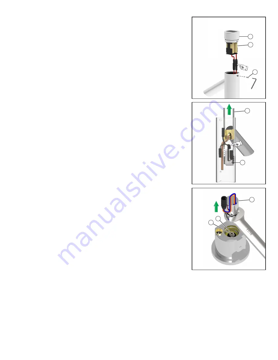
Remove the set screw (12) holding the solar cap (10) to the body assembly. Lift off the solar cap (10) and
battery pack (11) and disconnect them from the sensor.
6. There are two stainless steel locking pins (13) in the faucet that secure the sensor assembly (14). Pull out
the stainless steel pins up through the top of the faucet. It may be necessary to push the pins up from the
bottom of the faucet.
7. Replace the sensor assembly.
Note:
The sensor must be oriented with the wires going upwards.
8. Reinstall the locking pins (13).
9. Reconnect the solenoid cable.
10. There is a copper tube (9) in the body assembly that must be aligned to the outlet port (8) in the faucet base
so the body assembly can fit back over the faucet base.
11. Lock the faucet base to the body assembly using the set screw (4).
12. Reconnect the battery pack (11) and reinstall the solar cap (10) with set screw (12).
13. DEMD-321LF only: Reassemble the handle (1) and red/blue temperature indicator plug (2).
Note:
The temperature indicator plug should be oriented with the blue on the left and red on the right.
14. Restore water by opening the supply stop(s).
15. Activate faucet several times and check for leaks
Replacing the solenoid assembly (061328A)
(see Figures 10 - 12 & 15)
1.
Shut off the water at the supply stop(s).
2. Activate the faucet to relieve water pressure built up within the faucet.
3. DEMD-321LF only: Remove the side mixer handle (1) by pulling out the red/blue temperature indicator
plug (2) and handle screw (3).
4.
Remove the set screw (4) at the back of the faucet near the base, lift the body assembly off the faucet base
and disconnect the solenoid.
5. Use a 11/16” or 17mm wrench (1/4” thick max) to remove the solenoid assembly (15) from the faucet base.
Remove the diaphragm (16) and spring (17) if they are still in the faucet base.
6. Replace the solenoid assembly
7. Reconnect the solenoid cable.
8. There is a copper tube (9) in the body assembly that must be aligned to the outlet port (8) in the faucet base
so the body assembly can fit back over the faucet base.
9. Lock the faucet base to the body assembly using the set screw (4).
10. Reassemble the handle (1) and red/blue temperature indicator plug (2).
Note:
The temperature indicator plug (2) should be oriented with blue on the left and red on the right.
11. Restore water by opening the supply stop(s).
12. Activate faucet several times and check for leaks.
12
Fig. 13
10
11
Fig. 14
14
13
Fig. 15
15
17
16


