Chapter 5 Main Circuit Terminals
MS300 (IP66 / NEMA 4X)
5-2
DANGER
Securely fasten the main circuit terminal screws to prevent sparking caused
by loose screws due to vibration.
When needed, only use an inductive filter at the motor output terminals
U/T1, V/T2, W/T3 of the AC motor drive. DO NOT use phase-compensation
capacitors or L-C (Inductance-Capacitance) or R-C
(Resistance-Capacitance), unless approved by Delta.
DO NOT connect brake resistors directly to +1/DC+ to DC-, +2/B1 to DC- to
prevent damage to the drive.
Ensure proper insulation of the main circuit wiring in accordance with the
relevant safety regulations.
Main power terminals
DO NOT connect the three-phase drive to one-phase power. R/L1, S/L2
and T/L3 have no phase-sequence requirement; they can be connected in
any sequence.
Add a magnetic contactor (MC) at the power input to quickly cut off power
and reduce malfunction when activating AC motor drive protection function.
Both ends of the MC should have an R-C surge absorber.
Ensure that voltages and currents are within specification. Refer to Chapter
09 Specifications for details.
When using a general GFCI (Ground Fault Circuit Interrupter), select a
sensitivity greater than or equal to 200 mA and greater than or equal to 0.1
sec. operation time to avoid nuisance tripping.
Use conduits or shielded cables for the power wiring, and ground both ends
of the conduit or shielded cables.
DO NOT start or stop the drive by turning the power ON or OFF. Start and
stop the drive with the RUN/STOP command. If you still need to run or stop
the drive by turning power ON or OFF, it is strongly recommended that you
do so no more often than ONCE per hour.
To comply with UL standards, connect the drive to a three-phase three-wire
or three-phase four-wire Wye system type of mains power system.
Output terminals for main circuit
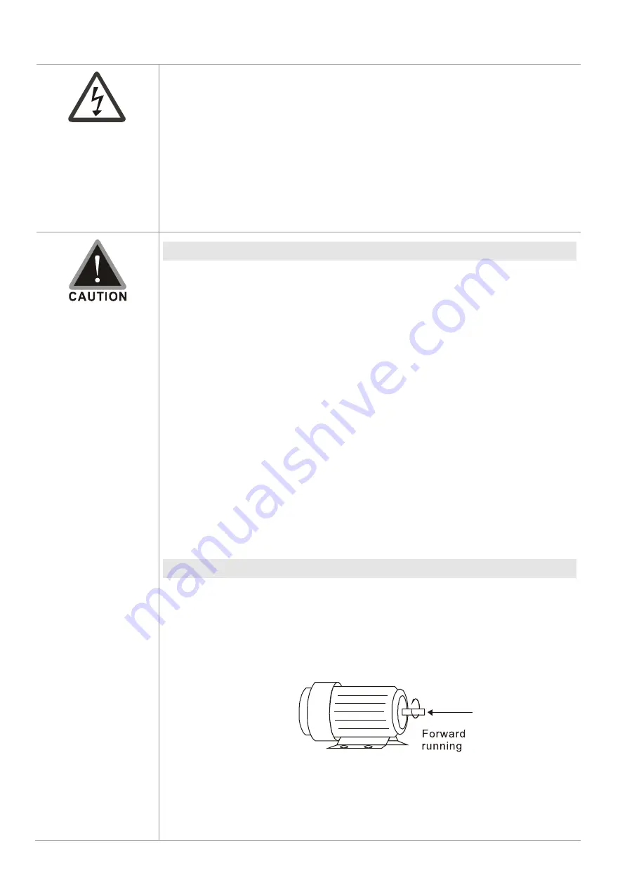
Use a well-insulated motor that is suitable for operation with an inverter.
When the AC drive output terminals U/T1, V/T2, and W/T3 are connected to
the motor terminals U/T1, V/T2, and W/T3 respectively, the motor rotates
counterclockwise (as viewed from the shaft end of the motor) when it
receives a forward operation command. To permanently reverse the
direction of rotation, exchange any two motor leads.
Figure 5-1
Summary of Contents for Compact Drive MS300 IP66/NEMA 4X Series
Page 3: ......
Page 10: ...Chapter 1 Introduction MS300 IP66 NEMA 4X 1 3 1 2 Model Name 1 3 Serial Number...
Page 18: ...Chapter 1 Introduction MS300 IP66 NEMA 4X 1 11 This page intentionally left blank...
Page 24: ...Chapter 2 Dimensions MS300 IP66 NEMA 4X 2 6 This page intentionally left blank...
Page 28: ...Chapter 3 Installation MS300 IP66 NEMA 4X 3 4 This page intentionally left blank...
Page 29: ...Chapter 4 Wiring MS300 IP66 NEMA 4X 4 1 Chapter 4 Wiring 4 1 System Wiring Diagram 4 2 Wiring...
Page 32: ...Chapter 4 Wiring MS300 IP66 NEMA 4X 4 4 4 2 Wiring Figure 4 2...
Page 34: ...Chapter 4 Wiring MS300 IP66 NEMA 4X 4 6 This page intentionally left blank...
Page 83: ...Chapter 7 Optional Accessories MS300 IP66 NEMA 4X 7 33 The drive with MKMX SWA...
Page 85: ...Chapter 7 Optional Accessories MS300 IP66 NEMA 4X 7 35 The drive with MKMX SWB...
Page 87: ...Chapter 7 Optional Accessories MS300 IP66 NEMA 4X 7 37 The drive with MKMX SWC...
Page 126: ...Chapter 10 Digital Keypad MS300 IP66 NEMA 4X 10 8 This page intentionally left blank...


