Dell SC4020 Deployment Manual Download Page 133

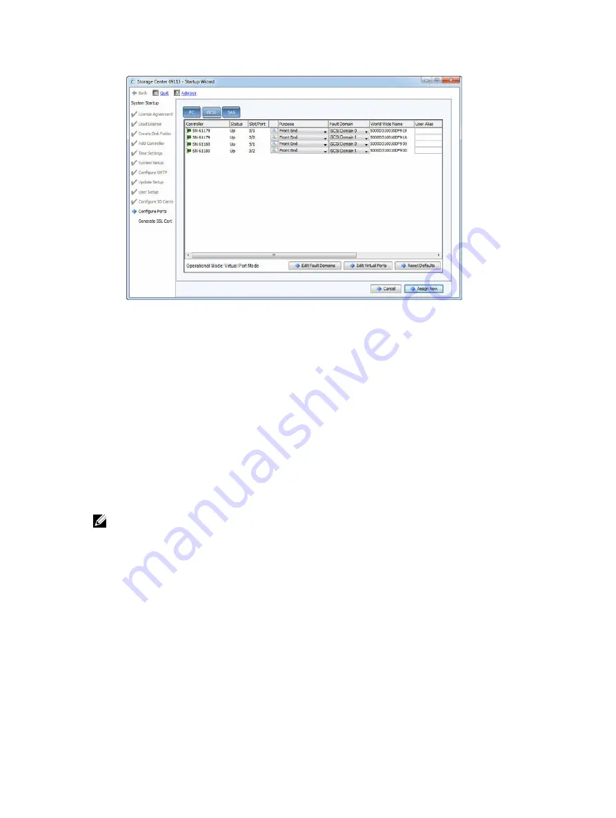
Figure 119. Configure the MGMT and iSCSI Ports

5.

(Optional) Change the preferred physical port for one or more virtual ports.
a. Click 

Edit Virtual Ports

. The wizard displays a list of virtual ports.

b. For each virtual port that you want to modify, select the preferred physical port in the 

Preferred 

Physical Port

 field.

c. When you are finished, click 

Apply Changes

. The 

iSCSI

 tab oepns.

6.

If you do not plan to use an iSCSI port, make sure that the port is not configured.
a. Set the 

Purpose

 field to 

Unknown

.

b. Set the 

Fault Domain

 field to 

<none>

.

c. (Optional) Type a descriptive name in the 

User Alias

 field.

Configure iSCSI Ports in Virtual Port Mode for an SC4020 with iSCSI Front-End Ports

Use the 

iSCSI

 tab on the 

Configure Ports

 page to create fault domains and configure the iSCSI ports.

About this task

The Startup Wizard displays the iSCSI and SAS tabs for an SC4020 with iSCSI front-end ports.

NOTE: The embedded iSCSI ports can be used for replication to another Storage Center or used for 

front

end connectivity to host servers.

Steps
1.

Click the 

iSCSI

 tab.

Set up Storage Center Software

133

Summary of Contents for SC4020

Page 1: ...Dell Storage Center SC4020 Storage System Deployment Guide ...

Page 2: ...d the problem WARNING A WARNING indicates a potential for property damage personal injury or death 2016 Dell Inc All rights reserved This product is protected by U S and international copyright and intellectual property laws Dell and the Dell logo are trademarks of Dell Inc in the United States and or other jurisdictions All other marks and names mentioned herein may be trademarks of their respect...

Page 3: ... Drives 24 SC4020 Storage System Drive Numbering 24 SC200 SC220 Expansion Enclosure Overview 25 SC200 SC220 Expansion Enclosure Front Panel Features and Indicators 25 SC200 SC220 Expansion Enclosure Back Panel Features and Indicators 26 SC200 SC220 Expansion Enclosure EMM Features and Indicators 27 SC200 SC220 Expansion Enclosure Drives 28 SC200 SC220 Expansion Enclosure Drive Numbering 28 SC280 E...

Page 4: ...s 75 Preparing Host Servers 75 SAS Virtual Port Mode 75 Four Servers Connected to Dual 12 Gb 4 Port SAS Storage Controllers 76 Four Servers Two HBAs Per Server Connected to Dual 12 Gb 4 Port SAS Storage Controllers 77 Two Servers Connected to Dual 12 Gb 4 Port SAS Storage Controllers 79 Labeling the Front End Cables 80 Cabling the Ethernet Management Port 81 Labeling the Ethernet Management Cables...

Page 5: ...Versions 98 Connect Power Cables and Turn On the Storage System 98 Establish a Serial Connection to the Top Storage Controller 100 Configure the Top Storage Controller 101 Establish a Serial Connection to the Bottom Storage Controller 103 Configure the Bottom Storage Controller 104 Start the Storage Center Startup Wizard 106 Completing the Storage Center Startup Wizard 109 License Agreement Page 1...

Page 6: ...closure to an SC4020 Deployed without Expansion Enclosures 153 Check the Disk Count before Adding an Expansion Enclosure 153 Add the SC280 Expansion Enclosure to the A Side of the Chain 154 Add the SC280 Expansion Enclosure to the B Side of the Chain 154 Adding an SC280 Expansion Enclosure to an SC4020 Deployed with One SC280 Expansion Enclosure 156 Check the Disk Count before Adding an Expansion ...

Page 7: ... Hat Enterprise Linux 175 Version 5 x 176 Version 6 x 176 SuSE Linux 177 Non Boot from SAN 177 Boot from SAN 177 C iSCSI Settings 179 Flow Control Settings 179 Ethernet Flow Control 179 Switch Ports and Flow Control 179 Flow Control 179 Jumbo Frames and Flow Control 179 Other iSCSI Settings 180 D Troubleshooting Storage Center Deployment 183 Troubleshooting the Serial Connection to a Storage Contr...

Page 8: ...connectivity Audience The information provided in this Deployment Guide is intended for use by Dell installers and Dell business partners Contacting Dell Dell provides several online and telephone based support and service options Availability varies by country and product and some services might not be available in your area To contact Dell for sales technical support or customer service issues g...

Page 9: ...ter System Manager Administrator s Guide Describes the Storage Center System Manager software that manages an individual Storage Center Dell Storage Center Software Update Guide Describes how to update Storage Center software from an earlier version to the current version Dell Storage Center Command Utility Reference Guide Provides instructions for using the Storage Center Command Utility The Comm...

Page 10: ...provide communication with servers and expansion enclosures Switches Dell offers enterprise class switches as part of the total Storage Center solution The SC4020 storage system supports Fibre Channel FC and Ethernet switches which provide robust connectivity to servers and allow for the use of redundant transport paths Fibre Channel FC or Ethernet switches can provide connectivity to a remote Sto...

Page 11: ...Architecture Options A Storage Center with an SC4020 storage system can be deployed in the following configurations An SC4020 storage system deployed without SC200 SC220 expansion enclosures Figure 1 SC4020 Storage System without Expansion Enclosures An SC4020 storage system deployed with one or more SC200 SC220 expansion enclosures Figure 2 SC4020 Storage System with Two SC200 SC220 Expansion Enc...

Page 12: ...t end connectivity Fibre Channel Hosts servers or Network Attached Storage NAS appliances access storage by connecting to the storage system Fibre Channel ports through one or more Fibre Channel switches Connecting host servers directly to the storage system without using Fibre Channel switches is not supported When replication is licensed the SC4020 can use the front end Fibre Channel ports to re...

Page 13: ...ront end connectivity may communicate with the following components of a Storage Center system Figure 4 Storage System with Fibre Channel Front End Connectivity Item Description Speed Communication Type 1 Server with Fibre Channel host bus adapters HBAs 8 Gbps or 16 Gbps Front End 2 Fibre Channel switch 8 Gbps or 16 Gbps Front End 3 SC4020 Storage System with FC front end connectivity 8 Gbps or 16...

Page 14: ...SCSI host bus adapters HBAs 1 Gb or 10 Gb Front End 2 Ethernet switch A pair of Ethernet switches is recommended for optimal redundancy and connectivity 1 Gb or 10 Gb Front End 3 SC4020 Storage System with iSCSI front end connectivity 1 Gb or 10 Gb Front End 4 SC200 SC220 Expansion Enclosures 12 Gbps per channel Back End 5 Remote Storage Center connected via iSCSI for replication 1 Gbps or 10 Gbps...

Page 15: ...d 4 SC200 SC220 Expansion Enclosures 6 Gbps per channel Back End 5 Remote Storage Center connected via iSCSI for replication 1 Gbps or 10 Gbps Front End 6 Management network computer connected to the storage system through the Ethernet switch Up to 1 Gbps System Administration 7 Computer connected to the SC4020 through a serial connection 115 200 Kbps System Administration Service and installation...

Page 16: ...hrow away the serial cables that come with the SC4020 Keep the serial cables with the SC4020 for troubleshooting purposes SC4020 Storage System Hardware The SC4020 storage system ships with Dell Enterprise Plus drives two redundant power supply cooling fan modules and two redundant storage controllers Each storage controller contains the front end back end and management communication ports of the...

Page 17: ...it ID display Displays the storage system identification number The default value for a new storage system is 01 5 Hard drives Can have up to 24 2 5 inch SAS hard drives SC4020 Storage System Back Panel Features and Indicators The back panel of the SC4020 contains the storage controller indicators and power supply indicators Figure 8 SC4020 Storage System Back Panel View Item Name Icon Description...

Page 18: ...ady Amber PSU has been removed or the storage system is having a problem communicating with the PSU Blinking amber PSU is in programming mode 6 AC power status indicator 2 Off AC power is off the power is on but the PSU is not in the storage system or a hardware fault is possible Steady green AC power is on Blinking green AC power is on and the PSU is in standby mode 7 DC power fault indicator 2 O...

Page 19: ... 1 Battery status indicator Blinking green on 0 5 sec off 1 5 sec Battery heartbeat Fast blinking green on 0 5 sec off 0 5 sec Battery is charging Steady green Battery is ready 2 Battery fault indicator Off No faults Blinking amber Correctable fault detected Steady amber Uncorrectable fault detected replace battery 3 MGMT port Slot 3 Port 1 Ethernet iSCSI port that is typically used for storage sy...

Page 20: ...ne USB 3 0 connector NOTE For engineering use only 12 Diagnostic LEDs 8 Green LEDs 0 3 Low byte hex POST code Green LEDs 4 7 High byte hex POST code 13 Serial port 3 5 mm mini jack Used to perform initial storage controller configurations In addition it is used to perform support only functions when instructed by Dell Technical Support 14 Two options Four Fibre Channel ports Slot 1 Port 1 Slot 1 P...

Page 21: ...0 5 sec Battery is charging Steady green Battery is ready 2 Battery fault indicator Off No faults Blinking amber Correctable fault detected Steady amber Uncorrectable fault detected replace battery 3 MGMT port Slot 3 Port 1 Ethernet iSCSI port that is typically used for storage system management and access to the BMC NOTE The MGMT port can be used as an iSCSI port for replication to another Storag...

Page 22: ...Diagnostic LEDs 8 Green LEDs 0 3 Low byte hex POST code Green LEDs 4 7 High byte hex POST code 13 Serial port 3 5 mm mini jack Used to perform initial storage controller configurations In addition it is used to perform support only functions when instructed by Dell Technical Support 14 Two iSCSI ports Slot 1 Port 1 and Slot 1 Port 2 with one LED per port Off No power Steady Amber Link Blinking Gre...

Page 23: ... use the RELP port as a front end connection to host servers a Flex Port license is required 5 SAS activity indicators There are four SAS PHYs per SAS port Off SAS PHY is not connected Steady green SAS PHY is connected but not active Blinking green SAS PHY is not connected nor active 6 Storage controller module status On Storage controller completed POST 7 Recessed power off button Not currently u...

Page 24: ... Indicators Item Control Feature Indicator Code 1 Drive activity indicator Blinking green Drive activity Steady green Drive is detected and has no faults 2 Drive status indicator Off Normal operation Blinking amber on 1 sec off 1 sec Drive identification is enabled Blinking amber on 2 sec off 1 sec Hardware firmware fault Steady amber Drive is safe to remove SC4020 Storage System Drive Numbering D...

Page 25: ...ure 15 SC200 Front Panel Features and Indicators Figure 16 SC220 Front Panel Features and Indicators Item Name Icon Description 1 Expansion enclosure status indicator Lights when the expansion enclosure power is on Off No power On steady blue Normal operation Blinking blue Storage Center is identifying the expansion enclosure On steady amber Expansion enclosure is turning on or was reset Blinking ...

Page 26: ...ot connected to AC power or has a fault condition 2 Power supply cooling fan indicator Amber Power supply cooling fan fault is detected Off Normal operation 3 AC power indicator Green Power supply module is connected to a source of AC power whether the power switch is on Off Power supply module is disconnected from a source of AC power 4 Power socket 2 Accepts a standard computer power cord 5 Powe...

Page 27: ... Expansion enclosure is not connected 5 SAS port B out Connects to a storage controller or to other SC200 SC220 expansion enclosures SAS ports A and B can be used for either input or output However for cabling consistency use port B as an output port 6 Port B link status Green All the links to the port are connected Amber One or more links are not connected Off Expansion enclosure is not connected...

Page 28: ...green Drive is detected and there are no faults 2 Drive status indicator Steady green Normal operation Blinking green on 1 sec off 1 sec Drive identification is enabled Steady amber Drive is safe to remove Off No power to the drive SC200 SC220 Expansion Enclosure Drive Numbering In an SC200 SC220 expansion enclosure the drives are numbered from left to right starting from 0 The Storage Center iden...

Page 29: ...2 SC280 Expansion Enclosure Front Panel Features and Indicators Item Name Panel Description 1 Drawer specific anti tamper locks Locks the drawer shut using a Torx T20 screwdriver until the red arrows point to the locked icon away from the center of the chassis 2 Drawer specific left and right side status indicators Sideplane OK Power Good Off Sideplane card or cable fault Green Sideplane card and ...

Page 30: ...ndby Off Expansion enclosure does not have power Green Expansion enclosure is on operational Amber Expansion enclosure is in standby mode not operational Module Fault Amber Hardware fault an LED may be lit on a PSU drawer DDIC fan module or I O module indicating the part at fault Logical Status Amber Change of status or fault from something other than the storage system itself this status is typic...

Page 31: ...e Icon Description 1 Optional cable retention positions 4 Locations for optional cable retention brackets 2 Expansion Enclosure Modules 2 Each EMM contains SAS ports and status indicators 3 Cooling fans 5 Fans that provide cooling for the expansion enclosure 4 Power supply units 2 2 8 kW power supply that provides power for the expansion enclosure 5 Optional cable retention positions 4 Locations f...

Page 32: ...Module OK Amber Module fault 2 Power LED Green steady Module OK Green flashing Vital product data VPD fault Off Module fault 3 Console port Not for customer use 4 SAS ports Connects to a storage controller or to another SC280 expansion enclosure 5 SAS activity indicators There are four SAS PHYs per SAS port Off SAS PHY is not connected Steady green SAS PHY is connected but no activity Blinking gre...

Page 33: ...ule OK Green Module OK 3 Fan fault Amber Loss of communication with the fan module or reported fan speed is out of tolerance SC280 Expansion Enclosure PSU Features and Indicators The SC280 includes two power supply units PSUs in two interface slots Figure 26 SC280 Expansion Enclosure PSU Features and Indicators Item Control Feature Icon Description 1 Release latch Press the release latch to remove...

Page 34: ...neither PSU has AC power If all three LEDs are on then the General Enclosure Management GEM software has lost communication with the PSU SC280 Expansion Enclosure Drives Dell Enterprise Plus hard disk drives HDDs and Dell Enterprise solid state drives eSSDs are the only drives that can be installed in SC280 expansion enclosures If a non Dell Enterprise Plus drive is installed the Storage Center pr...

Page 35: ...e slots are numbered 1 42 in the top drawer and 43 84 in the bottom drawer The Storage Center identifies drives as XX YY where XX is the unit ID of the expansion enclosure and YY is the drive position inside the expansion enclosure Figure 28 Hard Drive Drawers and Numbering 1 Bottom drawer 2 Top drawer About the SC4020 Storage System 35 ...

Page 36: ...tem 3 Rack rails 4 Front bezel Prepare the Installation Environment Make sure that the environment is ready for installing the Storage Center Rack Space The rack must have enough space to accommodate the storage system chassis expansion enclosures and switches Power Power must be available in the rack and the power delivery system must meet the requirements of the Storage Center Connectivity The r...

Page 37: ...low these safety precautions to avoid injury and damage to Storage Center equipment If equipment described in this section is used in a manner not specified by Dell the protection provided by the equipment could be impaired For your safety and protection observe the rules described in the following sections NOTE See the safety and regulatory information that shipped with each Storage Center compon...

Page 38: ...with a fully operational module power supply within 24 hours Unplug the storage system chassis before you move it or if you think it has become damaged in any way When powered by multiple AC sources disconnect all power sources for complete isolation Electrostatic Discharge Precautions Always follow electrostatic discharge ESD precautions to avoid injury and damage to Storage Center equipment Elec...

Page 39: ...ner that allows for expansion in the rack and prevents the rack from becoming top heavy NOTE Because the depth of the storage system is only 54 68 cm 21 53 in do not mount it below a piece of equipment with a full depth chassis Instead mount the storage system in a location from which you can access the rear of the storage system Steps 1 Secure the rails that are attached to both sides of the stor...

Page 40: ...ail to fit the rack and insert the two rail pins into the pin holes at the marked location at the back of the rack Figure 32 Extend the Rail 6 Insert a screw into the rack mounting screw hole at the back of the rack and tighten the screw to secure the rail to the rack 7 Repeat the previous steps for the second rail 8 Slide the storage system chassis onto the rails 40 Install the Storage Center Har...

Page 41: ... ear to access the screws b Tighten the screws to secure the chassis to the rack c Close the latch on each chassis ear Figure 34 Secure the Chassis to the Rack 10 If the Storage Center system includes expansion enclosures mount the expansion enclosures in the rack See the instructions included with the expansion enclosure for detailed steps Install the Storage Center Hardware 41 ...

Page 42: ...torage system with slot 0 and install drives from left to right 3 Slide the drive into the slot until the hard drive carrier makes contact with the backplane 4 Close the hard drive carrier handle to lock the hard drive in place 5 Continue to push firmly until you hear a click and the hard drive carrier handle fully engages 6 Insert drive blanks into any open slots in the chassis All of the drive s...

Page 43: ...e drive into the slot until the hard drive carrier contacts the backplane Figure 36 Installing Dell Enterprise Plus Hard Drives in an SC4020 Figure 37 Installing Dell Enterprise Plus Hard Drives in an SC4020 3 Close the hard drive carrier handle to lock the hard drive in place 4 Continue to push firmly until you hear a click and the hard drive carrier handle fully engages Install the Storage Cente...

Page 44: ...nclosure is 28 one full front row in the top drawer and one full front row in the bottom drawer Steps 1 Open the bottom drawer CAUTION If the expansion enclosure operates for too long depending on altitude with a drawer open it may overheat Overheating may cause a power failure and data loss which could invalidate the warranty a Push and hold both drawer latches toward the center of the drawer b P...

Page 45: ...ws from the front to the rear of the drawer a Hold the drive by the DDIC and slide it most of the way into the slot b Using both hands thumbs and forefingers apply downward pressure firmly and equally across the DDIC Figure 39 Inserting a Drive into the Drawer c While maintaining downward pressure slide the top plate of the DDIC toward the back of the drawer until it clicks into place Install the ...

Page 46: ...C fails to latch do not use it and request a replacement from Dell Technical Support If a faulty DDIC unlatches within a closed drawer you may not be able to open the drawer 3 Close the drawer after adding all of the DDICs a Locate the two lock release buttons situated midway along the runners on each side of the drawer b Press the lock release buttons inward and use your body to push the drawer t...

Page 47: ...Figure 41 Closing the Drawer WARNING Keep fingers clear of the chassis as the drawer is closed 4 Repeat the previous steps for the top drawer Install the Storage Center Hardware 47 ...

Page 48: ...ual WWN moves to another physical WWN in the same fault domain When the failure is resolved and ports are rebalanced the virtual port returns to the preferred physical port Virtual port mode provides the following advantages over legacy mode Increased connectivity Because all ports are active additional front end bandwidth is available without sacrificing redundancy Improved redundancy Fibre Chann...

Page 49: ...ers cannot be directly connected to storage system front end ports Multipathing If multiple active paths are available to a server the server must be configured for MPIO to use more than one path simultaneously iSCSI networks CHAP authentication must be disabled if converting from legacy mode to virtual port mode CHAP is not supported in virtual port mode Fibre Channel and Fibre Channel over Ether...

Page 50: ...ecting multiple primary and reserved ports to each Fibre Channel fabric In legacy mode each primary port on a storage controller is paired with a corresponding reserved port on the other storage controller During normal conditions the primary ports process I O and the reserved ports are in standby mode If a storage controller fails the primary ports fail over to the corresponding reserved ports on...

Page 51: ...CSI front end ports each storage controller must have two iSCSI front end ports to connect two paths to each Ethernet network Multipathing If multiple active paths are available to a server the server must be configured for MPIO to use more than one path simultaneously Fibre Channel zoning Fibre Channel switches must be zoned to meet the legacy mode zoning requirements Related links Fibre Channel ...

Page 52: ...ior Redundancy Failover Behavior Asymmetric Logical Unit Access ALUA If a storage controller becomes unavailable all the standby paths on the other storage controller become active Port redundancy In virtual port mode if a single port becomes unavailable the port can move to another available port in the same fault domain Storage controller redundancy If a storage controller becomes unavailable th...

Page 53: ...ending packets first down one path and then the other If a path becomes unavailable MPIO software continues to send packets down the functioning path NOTE MPIO is operating system specific and it loads as a driver on the server or it is part of the server operating system MPIO Behavior The server must have at least two FC or iSCSI ports to use MPIO When MPIO is configured a server can send I O to ...

Page 54: ...HBA port create a zone that includes the single HBA port WWPN and multiple Storage Center virtual WWPNs on the same switch Legacy Mode Include all Storage Center primary and reserve WWPNs in a single zone For each host server HBA port create a zone that includes the single HBA port WWPN and multiple Storage Center primary WWPNs on the same switch Fibre Channel Replication Storage Center System A V...

Page 55: ...l Storage Compatibility Matrix for a list of supported Fibre Channel HBAs Steps 1 Install Fibre Channel HBAs in the host servers NOTE Do not install Fibre Channel HBAs from different vendors in the same server 2 Install supported drivers for the HBAs and make sure that the HBAs have the latest supported firmware 3 Use the Fibre Channel cabling diagrams to cable the host servers to the switches Con...

Page 56: ... NOTE For the latest best practices see the Dell Storage Center Best Practices document on the Dell TechCenter site http en community dell com techcenter storage Virtual Port Mode Two Fibre Channel Fabrics with Dual 8 Gb 4 Port Storage Controllers Use two Fibre Channel FC fabrics with virtual port mode to prevent an unavailable port switch or storage controller from causing a loss of connectivity ...

Page 57: ...witch 1 3 Connect fault domain 2 shown in blue to fabric 2 Storage controller 1 port 2 to FC switch 2 Storage controller 1 port 4 to FC switch 2 Storage controller 2 port 2 to FC switch 2 Storage controller 2 port 4 to FC switch 2 Example Figure 45 Storage System in Virtual Port Mode with Dual 8 Gb Storage Controllers and Two FC Switches 1 Server 1 2 Server 2 3 FC switch 1 fault domain 1 4 FC swit...

Page 58: ...vailable the virtual ports on the offline storage controller move to physical ports on the other storage controller NOTE This configuration is vulnerable to switch unavailability which results in a loss of connectivity between the host servers and storage system Steps 1 Connect each server to the FC fabric 2 Connect fault domain 1 shown in orange to the fabric Storage controller 1 port 1 to the FC...

Page 59: ...hysical port in the same fault domain on the same storage controller If a storage controller becomes unavailable the virtual ports on the offline storage controller move to the physical ports on the other storage controller NOTE This configuration is vulnerable to switch unavailability which results in a loss of connectivity between the host servers and the storage system Steps 1 Connect each serv...

Page 60: ...age controller from causing a loss of connectivity between host servers and a storage system with dual 16 Gb 2 port storage controllers About this task In this configuration there are two fault domains two FC fabrics and two FC switches Each fault domain contains a set of primary and reserve paths P1 R1and P2 R2 To provide redundancy the primary port and corresponding reserve port in a fault domai...

Page 61: ...l com techcenter storage Legacy Mode Two Fibre Channel Fabrics with Dual 8 Gb 4 Port Storage Controllers Use two Fibre Channel FC fabrics with legacy mode to prevent an unavailable port switch or storage controller from causing a loss of connectivity between host servers and a storage system with dual 8 Gb 4 port storage controllers About this task In this configuration there are four fault domain...

Page 62: ...torage controller 2 port 3 to FC switch 2 5 Connect fault domain 4 shown in red to fabric 2 Primary port P4 Storage controller 2 port 4 to FC switch 2 Reserved port R4 Storage controller 1 port 4 to FC switch 2 Example Figure 49 Storage System in Legacy Mode with Dual 8 Gb Storage Controllers and Two Fibre Channel Switches 1 Server 1 2 Server 2 3 FC switch 1 Fault domain 1 4 FC switch 2 Fault doma...

Page 63: ...erver or storage controller port The reserved paths provide redundancy for an unavailable storage controller NOTE This configuration is vulnerable to switch unavailability which results in a loss of connectivity between the host servers and storage system Steps 1 Connect each server to the FC fabric 2 Connect fault domain 1 shown in orange to the fabric Primary port P1 Storage controller 1 port 1 ...

Page 64: ... the servers the primary paths provide redundancy for an unavailable server or storage controller port The reserved paths provide redundancy for an unavailable storage controller NOTE This configuration is vulnerable to switch unavailability which results in a loss of connectivity between the host servers and storage system Steps 1 Connect each server to the FC fabric 2 Connect fault domain 1 show...

Page 65: ...ent located on the Dell TechCenter http en community dell com techcenter storage Labeling the Front End Cables Label the front end cables to indicate the storage controller and port to which they are connected Prerequisites Locate the front end cable labels that shipped with the storage system About this task Apply cable labels to both ends of each cable that connects a storage controller to a fro...

Page 66: ...SI Host Servers Choose the iSCSI connectivity option that best suits the front end redundancy requirements and network infrastructure Preparing Host Servers Install the iSCSI host bus adapters HBAs or iSCSI network adapters install the drivers and make sure that the latest supported firmware is installed Contact your solution provider for a list of supported iSCSI HBAs Refer to the Dell Storage Co...

Page 67: ...r each iSCSI port The IP addresses must match the subnets for each fault domain CAUTION Correctly assign IP addresses to the HBAs or network adapters Assigning IP addresses to the wrong ports can cause connectivity issues NOTE If using jumbo frames they must be enabled and configured on all devices in the data path adapter ports switches and storage system e If the host uses network adapters for i...

Page 68: ...ode One iSCSI Network with Dual 10 GbE 2 Port Storage Controllers Use one iSCSI network with virtual port mode to prevent an unavailable port or storage controller from causing a loss of connectivity between the host servers and a storage system with dual 10 GbE 2 Port storage controllers About this task This configuration includes one fault domain one iSCSI network and one Ethernet switch Each st...

Page 69: ...e Ethernet switch Example Figure 55 Storage System in Virtual Port Mode with Dual 10 GbE Storage Controllers and One Ethernet Switch 1 Server 1 2 Server 2 3 Ethernet switch Fault domain 1 4 Storage system 5 Storage controller 1 6 Storage controller 2 Next steps Install or enable MPIO on the host servers NOTE For the latest best practices see the Dell Storage Center Best Practices document on the D...

Page 70: ... housing has an integral guide key that is designed to prevent you from inserting the transceiver module incorrectly Use minimal pressure when inserting an SFP transceiver module into an FC port Forcing the SFP transceiver module into a port may damage the transceiver module or the port The SFP transceiver module must be installed into a port before you connect the fiber optic cable The fiber opti...

Page 71: ...o the transceiver module to avoid recontamination Keep the protective cover in the transceiver module until you are ready to connect it to a fiber optic cable Cleaning Fiber Optic Cable Connectors Dell recommends using a can of compressed air methanol or isopropyl alcohol and a lens tissue to clean fiber optic cable connectors Prerequisites Do not allow the end of the fiber optic cable to contact ...

Page 72: ...llowing precautions Wear an antistatic discharge strap while handling transceiver modules Place transceiver modules in antistatic packing material when transporting or storing them Steps 1 Position the transceiver module so that the key is oriented correctly to the port in the storage controller Figure 57 Install the SFP Transceiver Module 1 SFP transceiver module 2 Fiber optic cable connector 2 I...

Page 73: ...ified in this document Do not stare into the laser beam CAUTION Transceiver modules can be damaged by electrostatic discharge ESD To prevent ESD damage to the transceiver module take the following precautions Wear an antistatic discharge strap while handling modules Place modules in antistatic packing material when transporting or storing them Steps 1 Remove the fiber optic cable that is inserted ...

Page 74: ...shipped with the storage system About this task Apply cable labels to both ends of each cable that connects a storage controller to a front end fabric or network or directly to host servers Steps 1 Starting with the top edge of the label attach the label to the cable near the connector Figure 59 Attach Label to Cable 2 Wrap the label around the cable until it fully encircles the cable The bottom o...

Page 75: ...lity Matrix for a list of supported SAS HBAs Steps 1 Install the SAS HBAs in the host servers NOTE Do not install SAS HBAs from different vendors in the same server 2 Install supported drivers for the HBAs and make sure that the HBAs have the latest supported firmware installed 3 Use the SAS cabling diagram to cable the host servers directly to the storage system NOTE If deploying vSphere hosts co...

Page 76: ...four 12 Gb front end SAS ports on each storage controller can connect to up to four host servers if each host server has one HBA with dual SAS ports About this task This configuration includes four fault domains spread across both storage controllers The storage controllers are connected to each host server using two SAS connections If a storage controller becomes unavailable all of the standby pa...

Page 77: ...ell com techcenter storage Four Servers Two HBAs Per Server Connected to Dual 12 Gb 4 Port SAS Storage Controllers A storage system with four 12 Gb front end SAS ports on each storage controller can connect to up to four host servers if each host server has two SAS HBAs About this task This configuration includes four fault domains spread across both storage controllers The storage controllers are...

Page 78: ...t server 3 a Connect a SAS cable from storage controller 1 port 3 to the first SAS HBA on host server 3 b Connect a SAS cable from storage controller 2 port 3 to the second SAS HBA on host server 3 4 Connect fault domain 4 shown in red to host server 4 a Connect a SAS cable from storage controller 1 port 4 to the first SAS HBA on host server 4 b Connect a SAS cable from storage controller 2 port 4...

Page 79: ... server 1 a Connect a SAS cable from storage controller 1 port 1 to the first SAS HBA on host server 1 b Connect a SAS cable from storage controller 2 port 1 to the first SAS HBA on host server 1 2 Connect fault domain 2 shown in blue to host server 1 a Connect a SAS cable from storage controller 1 port 2 to the second SAS HBA on host server 1 b Connect a SAS cable from storage controller 2 port 2...

Page 80: ... http en community dell com techcenter storage Labeling the Front End Cables Label the front end cables to indicate the storage controller and port to which they are connected Prerequisites Locate the pre made front end cable labels that shipped with the storage system About this task Apply cable labels to both ends of each cable that connects a storage controller to a front end fabric or network ...

Page 81: ... an Ethernet switch that is part of the management network About this task The management port provides access to the storage system software and is used to send emails alerts SNMP traps and SupportAssist diagnostic data The management port also provides access to the baseboard management controller BMC software Steps 1 Connect the Ethernet switch to the corporate management network shown in green...

Page 82: ...s or other computing devices separate the iSCSI traffic from management traffic using VLANs Labeling the Ethernet Management Cables Label the Ethernet management cables that connect each storage controller to an Ethernet switch Prerequisites Locate the Ethernet management cable labels that shipped with the SC4020 storage system About this task Apply cable labels to both ends of each Ethernet manag...

Page 83: ...ation is licensed the replication REPL port can be used to replicate data to another Storage Center About this task Connect the replication port of each storage controller to an Ethernet switch through which the Storage Center can perform iSCSI replication Steps 1 Connect the replication port on storage controller 1 to Ethernet switch 2 2 Connect the replication port on storage controller 2 to Eth...

Page 84: ... Center can perform replication NOTE In this configuration Storage Center system management traffic and iSCSI traffic use the same physical network ports For environments where the Storage Center system management ports are mixed with network traffic from other devices such as voice backups or other computing devices separate iSCSI traffic from management traffic using VLANs Steps 1 Connect embedd...

Page 85: ...oller from causing a loss of connectivity between the host servers and a storage system with dual Fibre Channel FC storage controllers About this task This configuration includes two fault domains two iSCSI networks and two Ethernet switches If a physical port or Ethernet switch becomes unavailable the storage system is accessed from the switch in the other fault domain If a storage controller bec...

Page 86: ...nel Storage Controllers 1 Corporate management network 2 Server 1 FC 3 Server 2 iSCSI 4 FC Switch 1 fault domain 1 for FC fabric 5 FC Switch 2 fault domain 2 for FC fabric 6 Ethernet switch 1 fault domain 1 7 Ethernet switch 2 fault domain 2 8 Storage system 9 Storage controller 1 10 Storage controller 2 5 To configure the fault domains and ports using see the Dell Storage Client Administrator s G...

Page 87: ...r environments where the Storage Center system management ports are mixed with network traffic from other devices such as voice backups or other computing devices separate iSCSI traffic from management traffic using VLANs Steps 1 Connect each server and Ethernet switch 1 to the corporate management network shown in green 2 Connect each server to both iSCSI networks 3 Connect embedded fault domain ...

Page 88: ...ault domains and ports see the Dell Storage Client Administrator s Guide Next steps Install or enable MPIO on the host servers NOTE For the latest best practices see the Dell Storage Center Best Practices document on the Dell TechCenter site http en community dell com techcenter storage 88 Connect the Front End Cabling ...

Page 89: ...only SAS port on one storage controller and ends at the initiator target SAS port the other storage controller You can connect multiple SC200 SC220 expansion enclosures to an SC4020 by cabling the expansion enclosures in series You can also connect up to two SC280 expansion enclosures to an SC4020 by cabling the expansion enclosures in series However the SC4020 does not support SC200 SC220 expansi...

Page 90: ...for an SC4020 storage system without expansion enclosures Table 7 Storage System Without Expansion Enclosures Path Connections Chain 1 A Side Orange Storage controller 1 port A to storage controller 2 port B Chain 1 B Side Blue Storage controller 2 port A to the storage controller 1 port B Back End Connections for an SC4020 Storage System With Expansion Enclosures An SC4020 supports up fourteen SC...

Page 91: ...SC220 expansion enclosure Table 8 SC4020 Storage System Connected to One SC200 SC220 Expansion Enclosure Path Connections Chain 1 A Side Orange 1 Storage controller 1 port A to the expansion enclosure top EMM port A 2 Expansion enclosure top EMM port B to storage controller 2 port B Chain 1 B Side Blue 1 Storage controller 2 port A to the expansion enclosure bottom EMM port A 2 Expansion enclosure...

Page 92: ...SC220 expansion enclosures Table 10 SC4020 Storage System Connected to Two SC200 SC220 Expansion Enclosures Path Connections Chain 1 A Side Orange 1 Storage controller 1 port A to expansion enclosure 1 top EMM port A 2 Expansion enclosure 1 top EMM port B to expansion enclosure 2 top EMM port A 3 Expansion enclosure 2 top EMM port B to storage controller 2 port B Chain 1 B Side Blue 1 Storage cont...

Page 93: ...enclosure Figure 77 SC4020 and One SC280 Expansion Enclosure 1 Storage system 2 Storage controller 1 3 Storage controller 2 4 Expansion enclosure The following table describes the back end SAS connections from an SC4020 to one SC280 expansion enclosure Table 11 SC4020 Connected to One SC280 Expansion Enclosure Path Connections Chain 1 A Side Orange 1 Storage controller 1 port A to the expansion en...

Page 94: ...he back end SAS connections from an SC4020 to two SC280 expansion enclosures Table 12 SC4020 Connected to Two SC280 Expansion Enclosures Path Connections Chain 1 A Side Orange 1 Storage controller 1 port A to expansion enclosure 1 left EMM port C 2 Expansion enclosure 1 left EMM port B to expansion enclosure 2 left EMM port A 3 Expansion enclosure 2 left EMM port C to storage controller 2 port B C...

Page 95: ...ystem to the expansion enclosures Prerequisites Locate the cable labels provided with the expansion enclosures About this task Apply cable labels to both ends of each SAS cable to indicate the chain number and side A or B Steps 1 Starting with the top edge of the label attach the label to the cable near the connector Figure 79 Attach Label to Cable 2 Wrap the label around the cable until it fully ...

Page 96: ...Figure 80 Wrap Label Around Cable 3 Apply a matching label to the other end of the cable 96 Connect the Back End Cabling ...

Page 97: ...igure the Storage Center software Prerequisites Before the Storage Center software can be configured the hardware must be connected and you must have the required materials and documents Hardware Configuration All hardware must be installed and cabled before beginning the software setup process If server connectivity is through Fibre Channel FC the FC switches must be configured and zoned during t...

Page 98: ...enclosures switches and servers Refer to the pre installation documents for information about site specific settings used during Storage Center configuration Required Software Versions Storage Center hardware has minimum software version requirements Table 14 Minimum Software Version Requirements Hardware Minimum Storage Center Software Version SC4020 storage system 6 7 5 SC200 SC220 expansion enc...

Page 99: ... storage system prepares to start up During the first minute the only indication that the storage system is powered on are the LEDs on the storage controllers After the 1 minute delay the fans and LEDs turn on to indicate that the storage controllers are starting up NOTE If the LEDs on a storage controller do not turn on the storage controller may not be fully seated in the storage system chassis ...

Page 100: ...lator program on the computer NOTE Make sure to enable logging in the terminal emulator If an issue occurs during the storage system deployment save a copy of the log file to allow for troubleshooting 3 Configure the serial connection in the terminal emulator as shown in the following table Table 15 Serial Connection Settings Setting Value Emulation VT220 Column Mode 132 Line Wrapping Off Connecti...

Page 101: ... controller 1 2 Bottom storage controller storage controller 2 Steps 1 In the terminal emulator press Enter several times to initiate the connection to the storage controller The terminal emulator displays the prompt SafeMode sn0 to indicate that the storage controller is in Safe Mode 2 Run the following command to enter the shellacess developer mode shellaccess developer 3 Run the following comma...

Page 102: ...cified the error message Gateway address not on eth0 subnet may appear when you try to exit Safe Mode If this error message appears re run the ifconfig inet eth0 IP address prefix length command to set the correct prefix length When the prefix length is not specified the value defaults to 32 c Run the following command to specify the gateway address ifconfig inet gateway gateway address Example if...

Page 103: ...ottom storage controller may not configure correctly CAUTION As the storage controller boots up a login prompt may appear in the terminal emulator Do not log in to the storage controller with the Admin account at this time Logging in with Admin account before the storage controller subsystems are fully initialized may cause the Admin account to become locked CAUTION Do not log in to the Storage Ce...

Page 104: ...mputer to the storage controller as described in Establish a Serial Connection to the Bottom Storage Controller About this task Configure the bottom storage controller with the higher HSN and IP addresses for the Ethernet management interface eth0 and Baseboard Management Controller BMC Figure 85 Storage Controllers 1 Top storage controller storage controller 1 2 Bottom storage controller storage ...

Page 105: ...ove are corrected type sm go to continue normal processing 4 Configure storage controller 2 with the information required to prejoin the storage controller a Run the following commands to set the HSN using the higher serial number provided in the pre installation documents platform init hsn set higher HSN Example platform init hsn set 10002 b Run the following command to specify an IP address and ...

Page 106: ...ight make the storage controller appear to be idle However the long pauses are part of the normal boot process When the storage controller finishes booting up the following message is displayed in the terminal emulator All subsystems initialized successfully CAUTION As the storage controller boots up a login prompt may appear in the terminal emulator Do not log in to the storage controller with th...

Page 107: ...edge any security messages NOTE The security messages that appear may differ depending on the browser used 3 If the Storage Center software and firmware need to be updated a dialog box opens that informs you it is mandatory to update the factory installed software and firmware to the latest version Figure 86 Mandatory Software and Firmware Update Dialog Box a Click Accept b Update the firmware and...

Page 108: ...he password expired page opens Figure 88 Change Admin Password 7 Enter a new password for the Admin user a Enter the old password which is mmm in the Old Password field b Enter a new password in the New Password and Confirm Password fields c Click Login The password is changed and you are logged in to the Storage Center System Manager 108 Set up Storage Center Software ...

Page 109: ...ystem The License Agreement page does not require a customer name or title when it is displayed for a new user 2 After reading the EULA click Accept to continue with setup The Load License page opens Load License Page Use the Load License page to upload the Storage Center license file The license file makes settings available depending on what features were purchased 1 Browse to the location of th...

Page 110: ...valid message is displayed 4 Click Continue The Create Disk Folder page opens Related links Troubleshooting Storage Center Licenses Create Disk Folder Page Use the Create Disk Folder page to assign disks to a folder in order to create a single pool of storage for volumes 1 Select the disks to include in the disk folder The Startup Wizard selects all available disks by default NOTE A Secure Data fo...

Page 111: ...ds selecting all available disks to maximize the benefits of Data Progression c Click Continue The Startup Wizard displays a page that allows you to select the disks to designate as hot spares 2 Review the hot spare disks that the Startup Wizard automatically selected A hot spare disk is held in reserve until a disk fails When a disk fails the hot spare replaces the failed disk The hot spare disk ...

Page 112: ... Modify the default folder name and enter a description in the Notes field Figure 92 Disk Folder Attributes 4 Optional Click Advanced to configure advanced disk folder options The wizard displays options for redundancy and datapage size NOTE The default managed disk folder settings are appropriate for most sites If you are considering changing the default settings contact Dell Technical Support fo...

Page 113: ... storage by default If a tier contains at least six managed disks of 2 6 TB or greater then that tier and all tiers below it are set to dual redundant storage and cannot be changed Single Redundant Protects against the loss of any one drive RAID 10 each disk is mirrored RAID 5 5 four data segments one parity segment per stripe RAID 5 9 eight data segments one parity segment per stripe Dual Redunda...

Page 114: ...ther way e Click Continue 5 Click Create Now The disk folder is created and the Add Controller page opens Add Controller Page If the storage controllers are configured with the correct pre join information the Storage Center Startup Wizard automatically joins the storage controllers 1 Storage Center joins the bottom storage controller to the top storage controller It then restarts the bottom stora...

Page 115: ...oller click Manually Add Controller Related links Joining Storage Controller Modules Manually Joining Storage Controllers Manually If the storage controllers fail to join automatically use the Add Controller page to join the bottom storage controller to the top storage controller 1 If the IPv6 address settings for the top storage controller are not configured a page is displayed on which you can c...

Page 116: ...Length field c Enter the IPv6 gateway address in the IPv6 Gateway field d Click Continue If the management network does not use IPv6 click Skip IPv6 Configuration 2 Click Add Controller The wizard prompts you for information about the bottom storage controller NOTE Information displayed in the following figure is for illustration only The values displayed are unique to each storage controller 116 ...

Page 117: ...nter Setup Wizard uses a predefined IP address and subnet mask for the Ether 1 IPC Interface The IP address values of the Ether 1 IPC Interface cannot be changed NOTE In the SC4020 storage system the IPC connection between the storage controllers is internal The IPC connection does not require external cabling 4 Click Continue The Startup Wizard displays a message that data and configuration infor...

Page 118: ...reboot When complete the Time Settings page opens Time Settings Page Use the Time Settings page to set the system time for the Storage Center 1 Set the time zone a From the Region drop down menu select the geographical region in which Storage Center is located b From the Time Zone drop down menu select the time zone in which Storage Center is located 118 Set up Storage Center Software ...

Page 119: ... IP address of an NTP server NOTE Accurate time synchronization is critical for replications Dell recommends using NTP to set the system time For more information see http support ntp org bin view Support WebHome 3 When the system time has been set click Continue The System Setup page oepns System Setup Page Use the System Setup page to specify the system name and management IP address for Storage...

Page 120: ... you to enable or disable the read and write cache Figure 103 Enable Read and Write Cache 5 Select or clear the checkboxes to enable or disable read and write cache NOTE Disable cache only if there will never be volumes that use cache If cache is left enabled on this page it can be disabled later for individual volumes For more information see the Storage Center System Manager Administrator s Guid...

Page 121: ...ld enter the IP address or fully qualified domain name of the SMTP email server Click Test server to verify connectivity to the SMTP server 2 In the Sender E mail Address field enter the email address of the sender Most SMTP servers require this address and it is used as the MAIL FROM address of email messages Figure 104 Configure SMTP Page 3 Click Advanced to configure additional SMTP settings fo...

Page 122: ...system compatibility select Send Extended Hello EHLO Instead of beginning the session with the HELO command the receiving host issues the HELO command If the sending host accepts this command the receiving host then sends it a list of SMTP extensions it understands and the sending host then knows which SMTP extensions it can use to communicate with the receiving host Implementing Extended SMTP ESM...

Page 123: ...ation when the download is complete Never check for software updates Phone Home not available Select this option to prevent the system from ever checking for updates This option is for secure sites at which SupportAssist is not available 2 Click Continue The User Setup page oepns To change the update options after completing the Storage Center setup select Storage Management System Update Configur...

Page 124: ...ettings for iSCSI ports 1 Enter the IP address for each iSCSI port in the IP Address field Figure 108 Configure IO Cards Page Uninitialized iSCSI I O ports have an IP Address of 0 0 0 0 2 Enter the subnet mask for each iSCSI port in the Subnet Mask field 3 Enter the gateway address for each iSCSI port in the Gateway field 124 Set up Storage Center Software ...

Page 125: ...Ports Page Use the Configure Ports page to configure the local ports for the Storage Center Select the connectivity modes and configure the front end and back end ports NOTE To configure the front end SAS ports of an SC4020 storage system see the Dell SC4020 Storage System Front End SAS Configuration Tech Note Select the Front End Connectivity Modes Select the front end connectivity mode for the F...

Page 126: ...cted operational mode Figure 111 Selected Operational Modes Configured 3 Click Continue to begin port initialization The Startup Wizard verifies the configuration and displays a confirmation page when the port configuration is generated 126 Set up Storage Center Software ...

Page 127: ...e Control Port for the iSCSI Fault Domain a Enter the IP address subnet mask gateway and port for the control port of the new iSCSI fault domain Check the pre installation documentation for this address b Click Continue The Startup Wizard generates the new iSCSI fault domain and the initial port configuration After the initial port configuration has been generated it is automatically validated 6 C...

Page 128: ...s for transport types in Virtual Port Mode Table 17 Port Purposes in Virtual Port Mode Port Purpose Description Unknown One of the following Port purpose is not yet defined The port is unused Front End Port is connected to servers and is used for the server I O path or the port is connected to another Storage Center and used for replication Back End Port is connected to an expansion enclosure The ...

Page 129: ...with Fibre Channel front end ports NOTE The embedded iSCSI ports can be used for replication to another Storage Center or used for front end connectivity to host servers Steps 1 Click the FC tab Figure 115 FC Ports Tab Virtual Port Mode 2 Create a fault domain for each FC fabric a Click Edit Fault Domains The wizard displays a list of the currently defined fault domains b Click Create Fault Domain...

Page 130: ...field to Unknown b Confirm that the Fault Domain field is set to none c Optional Type a descriptive name in the User Alias field Configure FC Ports in Legacy Mode Use the FC tab to create fault domains and configure the Fibre Channel ports About this task The Startup Wizard displays the FC iSCSI and SAS tabs for an SC4020 with front end Fibre Channel ports Steps 1 Click the FC tab Figure 116 FC Po...

Page 131: ...or an SC4020 with Fibre Channel Front End Ports Use the iSCSI tab on the Configure Ports page to create fault domains and configure the iSCSI ports About this task The Startup Wizard displays the FC iSCSI and SAS tabs for an SC4020 with Fibre Channel front end ports NOTE The embedded iSCSI ports can be used for replication to another Storage Center or used for front end connectivity to host server...

Page 132: ...to Front End b Set the Fault Domain field to the appropriate fault domain that you created c Optional Type a descriptive name in the User Alias field Figure 118 Configure the iSCSI Port 4 To use the embedded MGMT and iSCSI ports for iSCSI replication or front end connectivity configure the ports numbered Slot 3 Port 1 and Slot 3 Port 2 on each storage controller a Set the Purpose field to Front En...

Page 133: ...rt is not configured a Set the Purpose field to Unknown b Set the Fault Domain field to none c Optional Type a descriptive name in the User Alias field Configure iSCSI Ports in Virtual Port Mode for an SC4020 with iSCSI Front End Ports Use the iSCSI tab on the Configure Ports page to create fault domains and configure the iSCSI ports About this task The Startup Wizard displays the iSCSI and SAS ta...

Page 134: ...otes field type a description of the fault domain f Click Continue The dialog box displays a summary g Click Create Now h Repeat the previous steps to create additional fault domains as needed i When you are finished creating fault domains click Return The iSCSI tab opens 3 Configure the iSCSI front end ports numbered Slot 1 Port 1 and Slot 2 Port 2 on each storage controller a Set the Purpose fie...

Page 135: ...e appropriate fault domain c Optional Type a descriptive name in the User Alias field Figure 122 Configure Embedded iSCSI Ports 5 To use the embedded MGMT and REPL ports for iSCSI replication or front end connectivity configure the ports numbered Slot 3 Port 1 and Slot 3 Port 2 on each storage controller a Set the Purpose field to Front End b Set the Fault Domain field to the appropriate fault dom...

Page 136: ... 7 If you do not plan to use an iSCSI port make sure that the port is not configured a Set the Purpose field to Unknown b Set the Fault Domain field to none c Optional Type a descriptive name in the User Alias field Configure Front End SAS Ports The front end SAS ports of an SC4020 storage system cannot be configured using the Storage Center Startup Wizard To configure the front end SAS ports of a...

Page 137: ...me of the Storage Center The initial certificate shipped with Storage Center may not match the IP address or DNS host name assigned to the Storage Center If this is the case when connecting to Storage Center a message is displayed that identifies a mismatch between the certificate and the IP address or DNS host name of the Storage Center To correct this issue import or generate an SSL certificate ...

Page 138: ...eady been generated import the certificate Prerequisites The public key file must be in x 509 format Steps 1 Click Import An file window opens Figure 126 Import Certificate 2 Browse to the location of the public key pem file and select it 3 Click Next 138 Set up Storage Center Software ...

Page 139: ...by commas The wizard prepopulates the field with network information that it knows However it is likely that more site specific host names and addresses must be entered CAUTION The host names and addresses must match the Storage Center or you will be unable to reconnect to the Storage Center 3 Click Generate Now A new certificate is generated and the Storage Center System Manager session ends 4 Re...

Page 140: ...2 In the Summary tab click Send SupportAssist Information Now which is located under SupportAssist Actions in the Status pane The Send SupportAssist Information Now dialog box opens 3 Select the Storage Center Configuration and Detailed Logs checkboxes 4 Click OK Put the Storage Center Into Maintenance Mode Use Dell Storage Manager Client to put the Storage Center into maintenance mode after sendi...

Page 141: ...e Volume The Create Volume wizard opens d Type TestVol1 in the Name field e Set the volume size to 25 GB in the Size field f Click OK 4 Select the volume and click Map Volume to Server The Map Volume to Server dialog box opens a Select the server to which to map the volume from the Server list b Click Next c Click Advanced Options d Clear the Allow the Storage Center to automatically determine the...

Page 142: ... folder to the TestVol2 volume b During the copy process restart the bottom storage controller through which TestVol2 is mapped by selecting it from the Hardware tab and clicking Shutdown Restart Controller c Verify that the copy process continues while the storage controller restarts d Wait several minutes and verify that the storage controller has finished restarting Test MPIO Perform the follow...

Page 143: ... to normal operation Label SC200 SC220 Expansion Enclosures SC200 SC220 expansion enclosures have do not have displays to indicate the expansion enclosure ID assigned by Storage Center About this task To facilitate easy identification in the rack use the Dell Storage Manager Client to match each expansion enclosure ID to a Service Tag Locate the Service Tag on the back of each expansion enclosure ...

Page 144: ...tion dependent so some might not apply to your site Manage unmanaged disks Add Storage Center users including configuring Lightweight Directory Access Protocol LDAP Configure password rules for local users Create servers Configure user volume defaults Add Storage Center volumes Add a Storage Center login message 144 Perform Post Setup Tasks ...

Page 145: ...o form a chain 2 Use the Dell Storage Manager Client to connect to the Storage Center 3 Check the disk count of the Storage Center system before adding the expansion enclosures 4 Turn on the expansion enclosures When the drives spin up make sure that the front panel and power status LEDs show normal operation 5 Add the expansion enclosures to the A side chain 6 Add the expansion enclosures to the ...

Page 146: ...ber of drives that are currently accessible to the Storage Center 1 Connect to the Storage Center using the Dell Storage Manager Client 2 Select the Storage tab 3 In the Storage tab navigation pane select the Disks node 4 On the Disks tab record the number of drives that are accessible by the Storage Center Compare this value to the number of drives accessible by the Storage Center after adding an...

Page 147: ...e chain top EMM port B Figure 130 Connect the A Side Cables to the Expansion Enclosures 1 Storage system 2 Storage controller 1 3 Storage controller 2 4 Expansion enclosure 1 5 Expansion enclosure 2 Add the SC200 SC220 Expansion Enclosures to the B Side of the Chain Connect the expansion enclosures to one side of the chain at a time to maintain drive availability 1 Remove the B side cable shown in...

Page 148: ...n enclosure 1 5 Expansion enclosure 2 2 Cable the expansion enclosures to the B side of the chain a Connect a SAS cable from storage controller 1 port B to expansion enclosure 2 bottom EMM port B b Connect a SAS cable from storage controller 2 port A to expansion enclosure 1 bottom EMM port A 148 Adding or Removing an Expansion Enclosure ...

Page 149: ...on enclosure to an existing chain For maximum data protection add an expansion enclosure during a planned maintenance window NOTE When adding an expansion enclosure to a Storage Center with existing expansion enclosures add the new expansion enclosure to the end of the SAS chain Steps 1 Use the Dell Storage Manager Client to connect to the Storage Center 2 Check the disk count of the Storage Cente...

Page 150: ...tab 3 In the Storage tab navigation pane select the Disks node 4 On the Disks tab record the number of drives that are accessible by the Storage Center Compare this value to the number of drives accessible by the Storage Center after adding an expansion enclosure to the storage system Add an SC200 SC220 Expansion Enclosure to the A Side of the Chain Connect the expansion enclosure to one side of t...

Page 151: ...er 2 4 Expansion enclosure 1 5 New expansion enclosure 2 Add an SC200 SC220 Expansion Enclosure to the B Side of the Chain Connect the expansion enclosure to one side of the chain at a time to maintain drive availability 1 Disconnect the B side cable shown in blue from the expansion enclosure bottom EMM port B The A side cables continue to carry I O while the B side is disconnected Adding or Remov...

Page 152: ...e to connect expansion enclosure 1 bottom EMM port B to the new expansion enclosure 2 bottom EMM port A 3 Connect the B side cable that was disconnected in step 1 to the new expansion enclosure 2 bottom EMM port B Figure 136 Connect B Side Cables to the New Expansion Enclosure 1 Storage system 2 Storage controller 1 3 Storage controller 2 4 Expansion enclosure 1 152 Adding or Removing an Expansion...

Page 153: ...b b In the Storage tab navigation pane select the Disks node c Click Manage Unassigned Disks The Manage Unassigned Disks dialog box opens d From the Disk Folder drop down menu select the disk folder for the unassigned disks e To change which disks will be assigned to the disk folder click Change f To schedule a RAID rebalance select one of the following options To start a RAID rebalance after crea...

Page 154: ...a Connect a SAS cable from storage controller 1 port A to the expansion enclosure left EMM port C b Connect a SAS cable from storage controller 2 port B to the expansion enclosure left EMM port B Figure 138 Connect the A Side Cables to the Expansion Enclosure 1 Storage system 2 Storage controller 1 3 Storage controller 2 4 Expansion enclosure Add the SC280 Expansion Enclosure to the B Side of the ...

Page 155: ...he chain a Connect a SAS cable from storage controller 1 port B to the expansion enclosure right EMM port B b Connect a SAS cable from storage controller 2 port A to the expansion enclosure right EMM port C Figure 140 Connect the B Side Cables to the Expansion Enclosure Adding or Removing an Expansion Enclosure 155 ...

Page 156: ... B side chain 6 To manually manage new unassigned disks a Click the Storage tab b In the Storage tab navigation pane select the Disks node c Click Manage Unassigned Disks The Manage Unassigned Disks dialog box opens d From the Disk Folder drop down menu select the disk folder for the unassigned disks e To change which disks will be assigned to the disk folder click Change f To schedule a RAID reba...

Page 157: ...rom the expansion enclosure left EMM port B The B side cables continue to carry I O while the A side is disconnected Figure 141 Disconnect the A Side Cables from the Expansion Enclosure 1 Storage system 2 Storage controller 1 3 Storage controller 2 4 Expansion enclosure 1 3 Connect the A side cable that was disconnected in the previous step to the new expansion enclosure 2 left EMM port C 4 Use a ...

Page 158: ...sure 2 Add a Second SC280 Expansion Enclosure to the B Side of the Chain Connect an expansion enclosure to one side of the chain at a time to maintain drive availability 1 Disconnect the B side cable shown in blue from the expansion enclosure right EMM port B The A side cable continues to carry I O while the B side is disconnected 158 Adding or Removing an Expansion Enclosure ...

Page 159: ...xpansion enclosure 1 5 New expansion enclosure 2 2 Connect the B side cable that was disconnected in the previous step to the new expansion enclosure 2 right EMM port C 3 Use a new SAS cable to connect expansion enclosure 1 right EMM port A to the new expansion enclosure 2 right EMM port B Adding or Removing an Expansion Enclosure 159 ...

Page 160: ...ect the storage controllers or label the back end cables that connect the storage system to the expansion enclosures Prerequisites Locate the cable labels provided with the expansion enclosures About this task Apply cable labels to both ends of each SAS cable to indicate the chain number and side A or B Steps 1 Starting with the top edge of the label attach the label to the cable near the connecto...

Page 161: ... in Service To remove an expansion enclosure release the disks and disconnect the expansion enclosure from one side of the chain at a time CAUTION Before removing an expansion enclosure make sure that your data is backed up 1 Use the Dell Storage Manager Client to connect to the Storage Center 2 Release the disks in the expansion enclosure 3 Disconnect the A side chain a Disconnect the A side cabl...

Page 162: ... Center 2 Click the Hardware tab 3 In the Hardware tab navigation pane expand the enclosure to remove 4 Select the Disks node 5 Select all of the disks in the expansion enclosure 6 Right click on the selected disks and select Release Disk The Release Disk dialog box opens 7 Select Perform RAID rebalance immediately 8 Click OK When all of the drives in the expansion enclosure are in the Unassigned ...

Page 163: ...ler 2 4 Expansion enclosure 1 5 Expansion enclosure 2 3 Connect the A side cable to expansion enclosure 2 top EMM port A Figure 148 Reconnecting the A Side Cable to the Remaining Expansion Enclosure 1 Storage system 2 Storage controller 1 3 Storage controller 2 4 Expansion enclosure 1 Adding or Removing an Expansion Enclosure 163 ...

Page 164: ...while the B side is disconnected 2 Remove the B side cable between expansion enclosure 1 bottom EMM port B and expansion enclosure 2 bottom EMM port A Figure 149 Disconnecting the B Side Cables from the Expansion Enclosure 1 Storage system 2 Storage controller 1 3 Storage controller 2 4 Expansion enclosure 1 5 Expansion enclosure 2 3 Connect the B side cable to expansion enclosure 2 bottom EMM por...

Page 165: ...osure make sure that your data is backed up 1 Use the Dell Storage Manager Client to connect to the Storage Center 2 Release the disks in the expansion enclosure 3 Disconnect the A side chain a Disconnect the A side cables that connect the expansion enclosure to the storage system Click Next b Reconnect the A side cables to exclude the expansion enclosure from the chain Click Next to validate the ...

Page 166: ... the disks in the expansion enclosure 6 Right click on the selected disks and select Release Disk The Release Disk dialog box opens 7 Select Perform RAID rebalance immediately 8 Click OK When all of the drives in the expansion enclosure are in the Unassigned disk folder the expansion enclosure is safe to remove Disconnect the SC280 Expansion Enclosure from the A Side of the Chain Disconnect the A ...

Page 167: ...roller 1 3 Storage controller 2 4 Expansion enclosure 3 Connect the A side cable to storage controller 2 port B Figure 152 Connecting the A Side Cable to Storage Controller 2 1 Storage system 2 Storage controller 1 3 Storage controller 2 4 Expansion enclosure Adding or Removing an Expansion Enclosure 167 ...

Page 168: ...ile the B side is disconnected 2 Remove the B side cable between storage controller 2 port A and the expansion enclosure right EMM port C Figure 153 Disconnecting the B Side Cables from the Expansion Enclosure 1 Storage system 2 Storage controller 1 3 Storage controller 2 4 Expansion enclosure 3 Connect the B side cable to storage controller 2 port A The expansion enclosure is now disconnected and...

Page 169: ...re 154 Expansion Enclosure Disconnected from the B Side Cables 1 Storage system 2 Storage controller 1 3 Storage controller 2 4 Disconnected expansion enclosure Adding or Removing an Expansion Enclosure 169 ...

Page 170: ...170 Adding or Removing an Expansion Enclosure ...

Page 171: ...figuration For more information see the Dell Storage best practices Cisco Fibre Channel Cards Cisco manufactures HBA cards that are compatible with Dell Storage Center Configure Cisco fibre channel cards with the following settings Field Setting FCP Error Recovery Disabled default Flogi Retries 60 Flogi Timeout 4000 default Plogi Retries 60 Plogi Timeout 20000 default Port Down Timeout 10000 defau...

Page 172: ...Configure Qlogic HBA Settings Configure Qlogic HBA card settings to enable the server to communicate more effectively with Storage Center The following settings can be configured on any of the compatible Qlogic HBA cards from the Qlogic Fast UTIL BIOS or the Qlogic SANsurfer After configuring the settings based on the manufacturer of the HBA card configure the settings that apply to the operating ...

Page 173: ... volumes will persist after a Storage Center controller failover apply the following timeout values These settings are located in the mpathHBA file located in the opt xensource sm directory When finished save the file and reboot the server Table 19 Citrix XenServer HBA Settings for Versions 5 x to 6 2 Field Setting DEFAULT_TIMEOUT 60 MPATH_TIMEOUT 60 Version 6 5 For Citrix XenServer version 6 5 an...

Page 174: ...g be enabled for proper failover of Storage Center storage systems IBM AIX Configure the following settings in the Compellent Object Database Module ODM Path Control Module PCM for IBM AIX Table 21 IBM AIX HBA Settings Field Settings queue_depth hdisk attribute 32 rw_timeout hdisk 60 Microsoft Windows Server The default value for Windows Server 2003 Service Pack 1 and later is 60 seconds However t...

Page 175: ...Servers running Novell Netware require that the portdown value be reconfigured to allow enough time for the storage systems to fail over To the end of the Fibre Channel driver load line of nwserver startup ncf add LUNS ALLPATHS ALLPORTS PORTDOWN 60 Oracle Solaris Configure Oracle Solaris servers based on the version of Solaris running on the server NOTE Changes to Oracle Solaris settings require a...

Page 176: ...s_tmo 5 Version 6 x Changing HBA settings in RHEL version 6 x requires the creation of a new configuration file that contains the settings in the table below For Qlogic HBA cards create a configuration file in etc modprobe d named qla2xxx conf that contains one of the following parameters Qlogic HBA Settings Path Configuration Timeout Setting Single Path options qla2xxx qlport_down_retry 60 Multip...

Page 177: ...er of HBA card and path configuration Qlogic HBA Settings Path Configuration Timeout Setting Single Path options qla2xxx qlport_down_retry 60 Multipath options qla2xxx qlport_down_retry 5 Emulex HBA Settings Path Configuration Timeout Setting Single Path options lpfc lpfc_devloss_tmo 60 Multipath options lpfc lpfc_devloss_tmo 5 Boot from SAN Add one of the following lines to kernel line in the boo...

Page 178: ...178 HBA Server Settings ...

Page 179: ...rk should be set to ON Flow Control Dell recommends the following settings as best practice when enabling flow control A minimum of receive RX flow control should be enabled for all switch interfaces used by servers or storage systems for iSCSI traffic Symmetric flow control should be enabled for all server interfaces used for iSCSI traffic Storage Center automatically enables this feature NOTE To...

Page 180: ...iate for all interfaces that negotiate at full duplex and at the maximum speed of the connected port 1GbE or 10GbE If a switch cannot correctly auto negotiate at full duplex or at the maximum speed of the connection it should be hard set at full duplex and at the maximum speed of the connected port 1GbE or 10GbE MTU Verify the optimal MTU setting for replications The default is 1500 but sometimes ...

Page 181: ...Setting iSCSI Best Practice Disable multicast at the switch level for all iSCSI VLANs Set multicast storm control to enabled if available when multicast cannot be disabled iSCSI Settings 181 ...

Page 182: ...182 iSCSI Settings ...

Page 183: ...ossible Reason Solution No Disks Found by Startup Wizard No disks could be found attached to this Storage Center Need to update software and or firmware to use the attached expansion enclosure 1 Click Quit 2 Check for Storage Center updates and install the updates 3 Complete the Storage Center Startup Wizard Expansion enclosure firmware update fails Back end cabling is not redundant Check the back...

Page 184: ...he storage controller Troubleshooting the Storage Center Startup Wizard Table 28 Trouble with the Storage Center Startup Wizard and Updates Issue Possible Reason Solution Cannot complete the Storage Center Startup Wizard and cannot check for updates The management network may use a proxy server which blocks communication with the SupportAssist server Use the Command Line Interface CLI to configure...

Reviews: