


102
Installing System Components
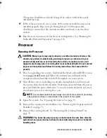
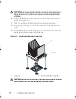
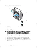
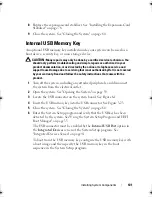
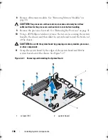
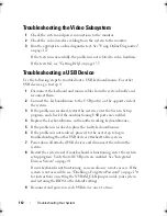
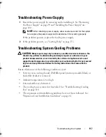
Figure 3-23. Removing or Installing a USB Memory Key
Chassis Intrusion Switch
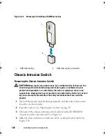
Removing the Chassis Intrusion Switch
CAUTION:
Many repairs may only be done by a certified service technician. You
should only perform troubleshooting and simple repairs as authorized in your
product documentation, or as directed by the online or telephone service and
support team. Damage due to servicing that is not authorized by Dell is not covered
by your warranty. Read and follow the safety instructions that came with the
product.
1
Turn off the system and attached peripherals, and disconnect the system
from the electrical outlet.
2
Open the system. See "Opening the System" on page 59.
3
Disconnect the chassis intrusion switch cable from the INTRUSION
connector on the system board. See Figure 6-1.
4
Slide the chassis intrusion switch out of the securing bracket notch. See
Figure 3-24.
1
USB memory key
2
USB memory key connector
1
2
Coaster_HOM.book Page 102 Monday, November 3, 2014 3:23 PM
Summary of Contents for PowerEdge T110 II
Page 9: ...Contents 9 Index 137 ...
Page 10: ...10 Contents ...
Page 33: ...About Your System 33 ...
Page 34: ...34 About Your System ...
Page 56: ...56 Using the System Setup Program and UEFI Boot Manager ...
Page 126: ...126 Troubleshooting Your System ...
Page 136: ...136 Getting Help ...
Page 142: ...142 Index ...


