


2 - 8
Chapter 2 Operation of Diag.
4. The Kind of Diag. and Contents of a Test
4.1 IOT Diag
4.1.1 Digital Input (DI) Test
This function checks whether the DI components operate normally or not.
The DI test is performed for all the DI components.
Exit operation of the DI test makes the control panel display the Customer diag. function menu.
During the DI test, other Customer diag. functions can not be performed simultaneously.
Therefore, the printer does not accept any operation except operations for the DI compo-
nents and exit operation of the DI test.
At the start of the DI test, number “ 0 ” is displayed on the control panel. This number is counted
up when a DI component is turned on from off, therefore it allows the user to know the component
is active.
When a paper jam is occurred, or an error message or code is displayed, execute this test to locate
the damaged parts.
The test will execute the DI Test codes of the components that are supposed to be faulty from the
error details. (Refer to each FIP on Chapter 1.)
Test result: NG (Go to each FIP or replace the parts.)
OK (Turn off/on the main power.)
4.1.2 Executing digital input (DI) test
1) Turn off the power.
2) Turn on the power while holding down “ ” and “ ” keys.
3) Release the fingers from these keys when “Diagnosing...” is displayed.
4) The “Customer Mode” and “IOT Diag” are displayed. (Entered the Diag. mode.)
5) Press “
3
” key.
6) Press “ ” key to select “Digital Input”, and then press “
3
” key.
7) Press “ ” or “ ” key to select the test item.
8) Press “
3
” key twice to execute the test.
- To exit the test or to return to one step higher menu, press the "CANCEL" key.
- From the menu which performed DI test, to return to one step higher menu, press the
"MENU" key.
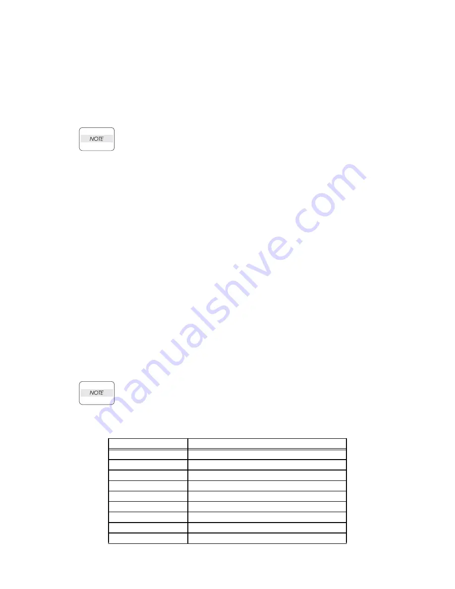
Parameters for the Digital Input Test are as follows.
Code
Components
DI-0
MPF No Paper Sensor
DI-1
CASSETTE 1 No Paper Sensor
DI-2
Regi Sensor
DI-3
Exit Sensor
DI-4
K Mode Sensor
DI-6
Side Switch
DI-7
Interlock Switch
DI-9
CASSETTE 2 No Paper Sensor
DI-a
CASSETTE 2 Paper Path Sensor
Summary of Contents for Color Laser Printer 2130cn
Page 1: ...Dell 2130cn Service Manual 22 April 2010 ...
Page 10: ...vii 4 5 2 Caution label for toner cartridges Rio00006KA ...
Page 11: ...viii Wsb00007KA ...
Page 12: ...ix Rio Service Manual Version 1 2008 02 29 4 5 3 Caution label for SSI and tray Rio00008KA ...
Page 13: ...x 4 5 4 Caution label for ROS Rio00009KA ...
Page 14: ...xi 4 5 5 Caution label for transfer belt and PHD unit Rio00005KA ...
Page 15: ...xii Rio00012KA ...
Page 16: ...xiii 4 5 6 Caution label for duplex Rio00013KA ...
Page 17: ...xiv Blank Page ...
Page 19: ...xvi Rio00011KB ...
Page 335: ...1 309 Chapter 1 Troubleshooting Wsb02025KA ...
Page 341: ...1 315 Chapter 1 Troubleshooting Chart Parallelism Perpendicularity ...
Page 342: ...1 316 Chapter 1 Troubleshooting Skew Linearity Magnification Error Registration ...
Page 406: ...Chapter 2 Operation of Diag Chapter 2 Operation of Diag CONTENTS ...
Page 409: ...2 3 Chapter 2 Operation of Diag Blank Page ...
Page 719: ...Chapter 5 Parts List Chapter 5 Parts List CONTENTS ...
Page 726: ...5 7 Chapter 5 Parts List Blank Page ...
Page 729: ...5 10 Chapter 5 Parts List PL1 2 Cover 2 2 Illustration ...
Page 731: ...5 12 Chapter 5 Parts List PL2 1 Paper Cassette Illustration ...
Page 733: ...5 14 Chapter 5 Parts List PL3 1 Paper Feeder 1 2 Illustration ...
Page 735: ...5 16 Chapter 5 Parts List PL3 2 Paper Feeder 2 2 Illustration ...
Page 739: ...5 20 Chapter 5 Parts List PL5 1 Dispenser Illustration ...
Page 741: ...5 22 Chapter 5 Parts List PL6 1 Transfer Fuser Illustration ...
Page 743: ...5 24 Chapter 5 Parts List PL7 1 Drive Illustration ...
Page 745: ...5 26 Chapter 5 Parts List PL8 1 Electrical 1 2 Illustration ...
Page 747: ...5 28 Chapter 5 Parts List PL8 2 Electrical 2 2 Illustration ...
Page 749: ...5 30 Chapter 5 Parts List PL9 1 Harness Illustration ...
Page 757: ...5 38 Chapter 5 Parts List PL12 2 250 Feeder Option 2 5 Illustration ...
Page 763: ...5 44 Chapter 5 Parts List PL12 5 250 Feeder Option 5 5 Illustration ...
Page 775: ...6 9 Chapter 6 Principles of Operation Blank Page ...
Page 777: ...6 11 Chapter 6 Principles of Operation Kmy06007KA ...
Page 782: ...6 16 Chapter 6 Principles of Operation 2 Paper Path 2 1 Paper Path Rio06010KA ...
Page 787: ...6 21 Chapter 6 Principles of Operation Blank Page ...
Page 799: ...6 33 Chapter 6 Principles of Operation Blank Page ...
Page 808: ...6 42 Chapter 6 Principles of Operation Blank Page ...
Page 825: ...6 59 Chapter 6 Principles of Operation Blank Page ...
Page 831: ...6 65 Chapter 6 Principles of Operation Blank Page ...
Page 874: ...Chapter 8 Printer Specifications Chapter 8 Printer Specifications CONTENTS ...


