background image


72 

Select the items to enter the corresponding display. 


X (

Mouse: Left Click X or Right Click to leave

)


Press this button to escape from this screen, and return to split-window display. 


Apply Button

 (Mouse: Left click)


Press this button to start back up (copy) or apply the revised settings. If it’s copying, 

press this button to return to the previous display. There will be a Copy status on the 
lower middle indicating that the selected video/audio is being archived to the storage 
device.


For DVD disc, the files won’t be written to the disc until the storage size 

reaches 1 GB or the user stop copying. Writing to the disc may take more than 1 
minute for every 100 MB (depending on the disc type). 


Stop Button

 (Mouse: Right Click)


Press  this  button  to  stop  copy  and  escape  from  this  screen.  It  will  return  to  the 

split-window display. 


The description for each item and its specific operations is as below: 


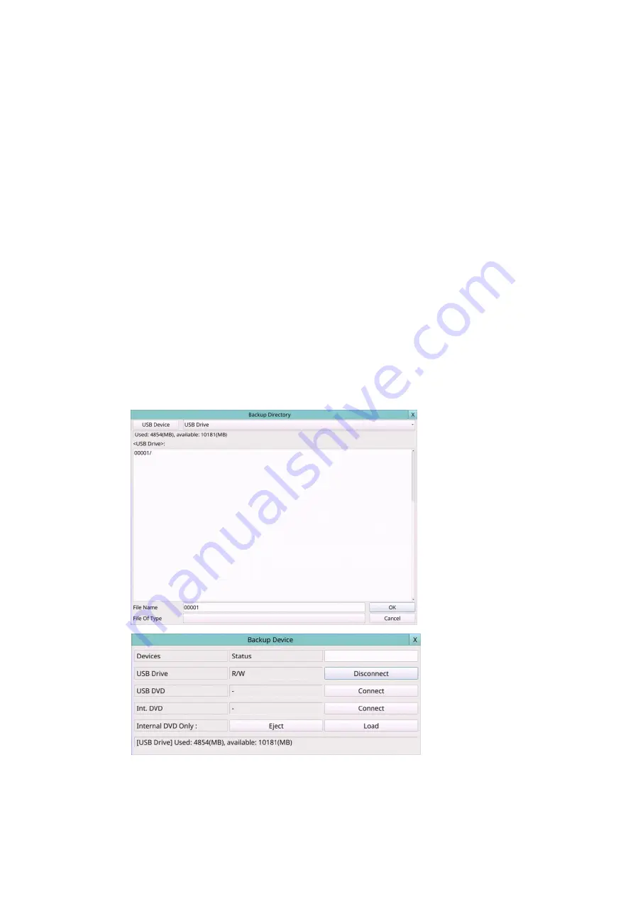
Backup  Device

  –  the  backup  device  connected  to  the  system.  Press 

USB  Device


(Mouse: Left click) 

on the Backup Directory display to call up 

Backup Device dialog


if  there’s  no  backup  device  connected. 

Mouse  Left  click

  buttons  to  select  the 

connected device. 

Connect the backup device before copying.


Connect/Disconnect

 – If the backup device is disconnected (as shown in Current 

Status),  please  plug  the  device  in  the  USB  port  and/or  insert  a  DVD  for  the  DVD 
device, and then 

Mouse Left click

 the 

Connect

 button to command the system to 

connect with it. If the device is already connected (EX. R/W - Read/write, as shown 
in Current Status), please 

Mouse Left click

 the 

Disconnect

 button to command the 

Summary of Contents for 16-CH

Page 1: ... 1 Hybrid DVR User s Manual Model 4 CH 8 CH 16 CH Before attempting to connect or operate this product please read these instructions carefully and save this manual for future use XVR_v1 2 0_20211026 ...

Page 2: ...with the instruction manual may cause harmful interference to radio communications Operation of this equipment in a residential area is likely to cause harmful interference in which case the users will be required to correct the interference at their own expense FCC Caution To assure continued compliance use only shielded interface cables when connecting to computer or peripheral devices Any chang...

Page 3: ...AINTENANCE OF THE PRODUCT FOR THE CASES INCLUDING BUT NOT LIMITED TO THE FOLLOWINGS ANY DAMAGE OR LOSS INCLUDING BUT WITHOUT LIMITATION DIRECT OR INDIRECT SPECIAL CONSEQUENTIAL OR EXEMPLARY ARISING OUT OF OR RELATING TO THE PRODUCT PERSONAL INJURY OR ANY DAMAGE CAUSED BY INAPPROPRIATE USE OR NEGLIGENT OPERATION OF THE USER UNAUTHORIZED DISASSEMBLE REPAIR OR MODIFICATION OF THE PRODUCT BY THE USER ...

Page 4: ...he power cord from being stepped on or pinched particularly at plugs convenient receptacles and the points where they exit from the apparatus Do not drop metallic parts through slots This could permanently damage the appliance Turn the power off immediately and contact qualified service personnel for service Handle the appliance with care Do not strike or shake as this may damage the appliance Do ...

Page 5: ...anced Network Setup 27 5 6 PTZ CONTROL 29 5 7 SYSTEM SHUTDOWN ADMINISTRATOR 31 6 SETUP ADMINISTRATOR 31 6 1 CAMERA SETUP 32 6 1 1 IPCam Encode Setup 35 6 1 2 IPCam Image Setup 36 6 1 3 Video Loss Setup 36 6 1 4 Motion eFence Privacy Mask Setup 38 6 2 ALARM SETUP 41 6 3 MAIN SEQ DISPLAY SETUP 43 6 4 SCHEDULED RECORD SETUP 44 6 5 HDD SETUP 47 6 5 1 HDD Format Clear 49 6 5 2 Advanced HDD Setup 52 6 6...

Page 6: ... REMOTE ACCESS 76 8 1 PC REMOTE ACCESS 76 8 2 PDA MOBILE PHONE REMOTE ACCESS CHROME WAP MODE 90 APPENDIX A TIME ZONE TABLE 91 APPENDIX B KEYBOARD CONTROL PROTOCOL 93 APPENDIX C MS WINDOWS HEM UTILITIES 95 APPENDIX D GPS FUNCTION IN REMOTE SOFTWARE WITH GOOGLE EARTH 100 APPENDIX E PROTOCOL CONVERTER FOR MULTIPLE POS 104 ...

Page 7: ...the buttons on the front panel The effective distance is about 10 meters without any obstacle 1 MODE Button Press this button to toggle between live mode and playback mode in main screen display In some dialogs this button is used as a miscellaneous function key At playing this button is used as slow backward 2 SEQ Button Press this button to switch to or return from SEQ display mode in main scree...

Page 8: ... in most circumstances In PTZ control this button is used to start stop the selected PTZ control mode 14 Split Windows Buttons In split window display press these buttons for next previous split window display In the others press these buttons to change the contents 15 DVR ID Selection Buttons DVR 1 4 Press these buttons to select the DVR to be controlled by the remote controller The remote contro...

Page 9: ... Connect the camera video input connectors to the video outputs from system cameras or other composite video sources via coaxial cables The internal 75Ω termination is always ON Main monitor Connect the main monitor output connector BNC VGA HDMI to a surveillance TV VGA monitor The TV VGA monitor displays selected live or recorded cameras in any available split window format Hard disk drive Make s...

Page 10: ...e a screwdriver to fix it as shown 4 Cover the machine Note 1 The HDD must be formatted before it can be used to record video audio Please refer to Section 6 5 1 to format the HDD Power Connect the power source to DC 12V USB Port Connect Mouse or USB pen drive ...

Page 11: ... Ethernet Connect the Ethernet connector to a standard twisted pair Ethernet cable for IP CAM and remote access via LAN or internet Please make sure to setup the related configurations as described in Section 5 5 and Section 6 1 USB 2 0 disk drives card reader etc If the user wants to use USB2 0 peripheral device to retrieve important recorded images and or audio please connect it to the USB2 0 po...

Page 12: ...ly RS 485 keyboard or Terminal Connect the RS 485 connector to a RS 485 keyboard controller or VT 100 terminal via the appropriate cables Please refer to the diagram above for the correct connection Please make sure to setup the RS 485 configurations as described in Section 6 8 accordingly Please refer to Appendix B for the Keyboard Control Protocol for the digital video recorder eSATA Hard Disk C...

Page 13: ...TMU295 Epson TMU300 Epson TMU675 Epson TMT882 Epson RPU420 and Epson MD332S For 1 to 1 POS please make sure to setup the RS 232 and RS 485 port correctly Section 6 8 For Multiple POS please make sure to setup the ID of protocol converter I 7524 correctly Appendix E and then setup the RS 232 and RS 485 port correctly Section 6 8 Top figure 1 to 1 bottom figure RS 232 Multiple 1 to many ...

Page 14: ...played in the lower right corner The screen messages in the lower left corner shown while a certain event occurs The system states from right to left are described as the followings 1 Normal recording percentage 2 Alarm recording percentage 3 Manual record ON OFF shown for ON 4 Backup state Backup status shown 5 Number of remote connections The number in the icon is the current number of connectio...

Page 15: ...dministrator can set up the login name and password for each user Please refer to Section 6 6 for Password Setup The Operator can operate live video display the Supervisor live video display image playback and archive and the Administrator everything To Login Logout system right click the mouse in split window to call up Menu display then Left click the mouse to select the Login Logout In Menu dis...

Page 16: ...Digital Zoom mode Please refer to Section 4 4 Digital Zoom for the detailed operations in Digital Zoom mode SEQ Mouse Press this button to switch to or return from SEQ display mode In SEQ display mode each page in the sequence will be shown for the preset page dwelling time sequentially When the SEQ starts ends the SEQ icon will be displayed in the upper right corner of the screen for about three ...

Page 17: ...ne of the video window to move the yellow zone zoom window if it s shown in the video window b Click in the video window to navigate the video window around if the zoom factor is X2 or X4 ENTER Mouse Click in the video window Click in the yellow zone of the video window to zoom in the zoom window from X1 to X2 or from X2 to X4 if the zoom window is shown in the video window X2 Mouse Press this but...

Page 18: ...n the gray out icon Please refer to Section 4 2 for Login Logout display The user s operations are described as the followings ENTER Mouse Click in the menu item Press this button to enter the detailed display of the highlighted option For the details of each option please refer to the following sections X Mouse Left Click X or Right Click to leave Press this button to escape from Menu display and...

Page 19: ...click the mouse to select the Volume Mouse In Menu display the Volume Control will be shown The general operations are as below Mouse Click in the respective item Select the items to set X Mouse Left Click X or Right Click to leave Press this button to escape from this screen and return to Menu display If the contents have been modified a Save dialog will be shown to ask the user to save the chang...

Page 20: ...d items Factory Reset This Mouse Left click the mouse to select this Press this button to reset the settings for this camera to factory default values Factory Reset All Mouse Left click the mouse to select this Press this button to reset the settings for all cameras to factory default values Restore Mouse Left click the mouse to select this Press this button to restore the values X Mouse Left Clic...

Page 21: ...Press this button to escape from this screen If the contents have been modified a Save dialog will be shown press YES to exit and save CANCER to exit without saving Please note that the display may not be able to support the resolution newly selected and hence the display will show nothing If so please press CANCER or wait for 15 seconds to restore the original resolution If users press YES to acc...

Page 22: ...operations Net Type Static IP PPPoE or DHCP For internet access please make sure the below IP Address is a public IP address otherwise 1 a router with public IP address is required and the router must be setup for port mapping forwarding to the DVR or 2 CMS server must be used Sec 5 5 4 P2P if enabled the QR code of the DVR will be shown on the upper right corner and users can scan it to access th...

Page 23: ...stem Please follow the Text Input method described in Section 4 1 to modify this item DDNS Username DDNS username for the DVR for Static IP PPPoE or DHCP Please follow the Text Input method described in Section 4 1 to modify this item DDNS Password DDNS password for the DVR for Static IP PPPoE or DHCP Please follow the Text Input method described in Section 4 1 to modify this item Note If DDNS Typ...

Page 24: ...e mail transmission The default value is 25 Please follow the Text Input method described in Section 4 1 to modify this item Authentication whether the SMTP mail server requires authentication Username username if the SMTP mail server requires authentication Please follow the Text Input method described in Section 4 1 to modify this item Password password if the SMTP mail server requires authentic...

Page 25: ... operations FTP Server FTP server web IP address with or without directory path Please follow the Text Input method described in Section 4 1 to modify this item FTP Port the FTP port The default value is 21 Please follow the Text Input method described in Section 4 1 to modify this item Username username for this DVR unit in the FTP server Please follow the Text Input method described in Section 4...

Page 26: ...word password if requested by ISP Please follow the Text Input method described in Section 4 1 to modify this item Dial String the 3G dial command Please follow the Text Input method described in Section 4 1 to modify this item APN Optional APN info Please follow the Text Input method described in Section 4 1 to modify this item PIN PIN associated with the SIM card used Please follow the Text Inpu...

Page 27: ...utton to escape from this screen and return to Network Setup display If the Save dialog is shown press YES to exit and save CANCER to exit without saving Following is a brief description for each item and its specific operations Control Port the control port for remote access The default value is 67 Please follow the Text Input method described in Section 4 1 to modify this item Data Port the data...

Page 28: ...d in the CMS Server if CMS Server described below is to be connected with the DVR Please follow the Text Input method described in Section 4 1 to modify this item CMS Server URL 1 2 the URL Uniform Resource Locators for the CMS Server 1 and 2 The DVR will connect with up to two CMS servers automatically once it s running Please note that with this feature the DVR needs not to be a web server while...

Page 29: ...a it can enter PTZ control mode In PTZ control mode the user s operations can be divided into general operations and miscellaneous function specific operations and are described as the followings General operations X Mouse Left Click X or Right Click to leave Press this button to exit PTZ control mode Menu Mouse Left click the button Press this button to Open UTC control menu of the camera Mouse L...

Page 30: ...stop Auto Pan set start position set end position Sequence Select Value Run Stop SEQ dwell time is shown in the center If SEQ mode is on the camera will go to preset position 0 9 or 1 10 sequentially change dwell time start stop SEQ mode Preset Select Value Set Clear Preset location is shown in the right lower corner change Preset location set Preset location clear Preset location Pan Speed Select...

Page 31: ...wn 6 Setup Administrator Left click the mouse to select the Setup Mouse In Menu display the Setup Menu will be shown To enter Setup Menu display of the system please login as Administrator first The user s operations are described as the followings The general operations are as below Mouse Left Click in the respective item Select the items to set X Mouse Left Click X or Right Click to leave Press ...

Page 32: ...a if it s a PTZ camera The PTZ ID has to be consistent with the setting of this camera Please refer to the manual of the camera for the ID setting Change the value N A 0 255 for RS 485 or non 485 for IP CAM or data over coax The default setting is N A Not Available which means that it s not a PTZ camera All Cameras Compression Analog only Compression ratio of Normal or High High compression ratio ...

Page 33: ...the IP CAM Please note that camera setup is not supported for RTSP However live network view record and playback are supported but users need to configure the bit rate and the frame rate of main dual stream manually so that the Max Incoming bandwidth won t be exceeded For plug and play please note that it is supported for DHCP or static IP of IP CAM but only two predefined sets of username passwor...

Page 34: ...e refer to Section 6 1 1 for the details Event Record IPS the IPS Images Per Second for analog camera if certain event Motion Alarm occurs for this camera This camera will be recorded at this rate for Post record time since the event occurs The Event Record IPS for IP camera please refer to Section 6 1 1 for the details Pre record IPS the pre record IPS for analog camera if certain event Video Los...

Page 35: ... encoding settings for the camera The general operations are as below Mouse Click in the respective item Select the items to set X Mouse Left Click X or Right Click to leave Press this button to escape from this screen and return to IPCam Setup Menu display If the contents have been modified a Save dialog will be shown to ask the user to save the changes press YES to exit and save CANCER to exit w...

Page 36: ... this screen and return to Camera Setup display If the contents have been modified a Save dialog will be shown to ask the user to save the changes press YES to exit and save CANCER to exit without saving Following is a brief description for each item and its specific operations Camera Press the Numeric to select the camera Duration response duration to define at most how long in seconds the Alarm ...

Page 37: ...m Alarm Out to define which Alarm Output will be triggered when this event is triggered Buzzer to activate the internal Buzzer or not when video loss of this camera is detected Log to log to event logs or not Screen Message to display the event message on the screen or not E mail to send the event e mail to remote station or not The e mail will be sent to the predefined receivers at the moment whe...

Page 38: ...ids and the area with is the area which will be detected for motion while transparent grids not detected for motion The general operations are as below Mouse Click in the respective item Select the items to set X Mouse Left Click X or Right Click to leave Press this button to escape from this screen and return to Camera Setup display If the contents have been modified a Save dialog will be shown t...

Page 39: ...elect the camera Sensitivity The sensitivity 1 10 for the motion detection of this camera Mouse Left click and drag Draw the eFence line Up to 4 lines can be drawn Mouse Left click Click on the eFence line to select it Delete Click to delete the selected eFence line Test Click on this button to test The color of the eFence line will be changed if it s crossed by an object of reasonable size Click ...

Page 40: ...st field if motion or eFence is detected for this camera For more details about preset locations please refer to Section 5 6 PTZ Control Pre record to define how long before motion or eFence is detected this camera shall be intensively recorded at Pre record IPS Please note that the actual pre record time may be shorter than the value set if the total size of the pre record pictures exceeds the pr...

Page 41: ...o select the Alarm In No Source used to setup the Alarm Input Source including Source Type which is N A Local or IP CAM Source ID which is 1 4 8 for Local or the camera ID for IP CAM and Sub ID which is 1 4 8 16 for IP CAM Normal State N A Close Open Close Level or Open Level Please check the signal type normally close or normally open connected to the alarm input terminal on the rear panel of the...

Page 42: ...pre record buffer size of the system Post record to define how long after this alarm input is triggered or returns to normal the Focus Camera shall be intensively recorded at Event Record IPS Alarm Out to define which Alarm Output will be triggered when this alarm input is triggered Alarm Output Source Setup up to 32 alarm outputs can be selected and the definitions are similar to alarm inputs Buz...

Page 43: ... modified a Save dialog will be shown to ask the user to save the changes press YES to exit and save CANCER to exit without saving Following is a brief description for each item and its specific operations Device Type select to set Main Monitor or Call Monitor Window Type select to set the split window Dwell Time the dwell time 3 60 seconds for each page of this display type Total Pages total page...

Page 44: ...Event to switch the main monitor to the video of the event camera or not 6 4 Scheduled Record Setup Left click the mouse to select the Schedule Record Mouse In Setup Menu display the Schedule Record Setup will be shown The Scheduled Record Setup allows the administrator to define when and how to record for the system There are up to 16 time segments T1 T16 for each weekday ...

Page 45: ...s specific operations Mode the schedule below applies to All cameras or Individual camera Camera select the camera if Individual is selected Start the start time of this time segment increment at 30 minutes The end time of this time segment is implicitly set as the start time of next time segment or the start time of the first time segment of the same weekday if it s the last one Example If the us...

Page 46: ...uled Record will be updated accordingly If the contents have been modified a Save dialog will be shown to ask the user to save the changes press YES to exit and save CANCER to exit without saving COPY Press this button to copy the settings of the focus camera to all the following cameras EX focus camera is 2 its schedule settings will be copied to those of the cameras 3 8 Color Mouse Left click Pr...

Page 47: ...the last HDD in the system The general operations are as below Mouse Click in the respective item Select the items to set X Mouse Left Click X or Right Click to leave Press this button to escape from this screen and return to Setup Menu display If the contents have been modified a Save dialog will be shown to ask the user to save the changes press YES to exit and save CANCER to exit without saving...

Page 48: ... the user presses the Alarm Reset button HDD Full Action actions when Alarm Normal Record disk drive capacity reaches the end of the last HDD Duration response duration to define at most how long in seconds the Alarm Out relay and the Buzzer will keep being triggered after the corresponding partition Alarm Record or Normal Record is full The value means forever Alarm Out to define which Alarm Outp...

Page 49: ... Click X or Right Click to leave Press this button to escape from this screen and return to HDD Setup display If the contents have been modified a Save dialog will be shown to ask the user to save the changes press YES to exit and save CANCER to exit without saving Format Mouse Left click Press this button to format the HDD A confirmation dialog will be shown on the screen Press YES to confirm or ...

Page 50: ...is physical format function to format the HDD for the first time Note The HDD will be physically formatted and partitioned with default record size 100 for Alarm record and 0 for Normal record All the previously recorded contents will be cleared Following is a brief description for each item and its specific operations Size GB the total storage in GB Giga Byte for the HDD if it has been formatted ...

Page 51: ...ER to exit without saving Please note that if the NAS settings are changed the user will be asked to reboot the system for the new settings to take effect The NAS device will be always the last storage in the HDD list Type NFS or N A URL the URL Uniform Resource Locators for the NAS device Please follow the Text Input method described in Section 4 1 to modify this item Path the path in the NAS dev...

Page 52: ... operations Duration response duration to define at most how long in seconds the Alarm Out relay and the Buzzer will keep being triggered after HDD failure is detected The value 3 seconds 60 minutes discrete for Forever Alarm Out to define which Alarm Output will be triggered when this event is triggered Alarm Output Source Setup up to 32 alarm outputs can be selected and the definitions are simil...

Page 53: ...to 18 user accounts There is one factory preset login name password aa 11 at Administrator level The user can use it to login the system for the first time The general operations are as below Mouse Click in the respective item Select the items to set X Mouse Left Click X or Right Click to leave Press this button to escape from this screen and return to Setup Menu display If the contents have been ...

Page 54: ...ase follow the Text Input method described in Section 4 1 to modify this item Password this item accepts numbers only Please follow the Text Input method described in Section 4 1 to modify this item Level the password level Administrator Supervisor Operator or Customized for this user Adv press Mouse Left click to call up Advanced User Setup as shown below The Advanced User Setup allows the admini...

Page 55: ...SD Display to enable the user to change GPS POS OSD Display if checked Mouse Left click to check uncheck this item Volume to enable the user to change volume if checked Mouse Left click to check uncheck this item Video Adjustment to enable the user to do video adjustment operation if checked Mouse Left click to check uncheck this item Display to enable the user to change display settings if checke...

Page 56: ...S 232 485 Setup if checked Mouse Left click to check uncheck this item Setup Network to enable the user to do Network Setup if checked Mouse Left click to check uncheck this item Setup Factory Defaults to enable the user to restore factory defaults to all setup related configurations if checked Mouse Left click to check uncheck this item Others Software Upgrade to enable the user to upgrade DVR so...

Page 57: ...thout saving Following is a brief description for each item and its specific operations Time Zone Select the time zone for the system Please refer to Appendix A for the time zone table Daylight Saving Time Mouse Left click to check uncheck this item The default value is set by selecting a different time zone but the user may check uncheck this item if the default setting is checked Synchronization...

Page 58: ...tall the remote software if it is to be used to access the system Factory Reset reset all the settings to factory default values Backup backup the configurations and QR code image of this unit to the corresponding USB device The user may enter the directory to back up the configurations to Note The QR code image can be used to connect to device via select this image from HEM device list Restore re...

Page 59: ...g is a brief description for each item and its specific operations Device Type PTZ Keyboard GPS POS PTZ Keyboard or N A Not Available Press button to change the type Model PTZ model for PTZ and PTZ Keyboard Keyboard model GPS protocol or POS printer type of the connected devices The PTZ models supported include Pelco D protocol Dome SamSung SCC 641P Kalatel Cyber Dome PIH series Dynacolor Bosch Au...

Page 60: ...hange the value Stop Bit press button to change the value Parity Odd Even or None Press button to change the value DVR Camera ID for PTZ Keyboard the device ID for this digital video audio recorder and it must not conflict with the other devices connected in the same control port for GPS POS the Camera ID to receive the GPS POS data For Multiple POS please set the DVR Camera ID setting as Multiple...

Page 61: ...nu display If the Save dialog is shown press YES to exit and save CANCEL Mouse Right Click to exit without saving Following is a brief description for each item and its specific operations Title On Off Set display camera title on split window or not Time On Off Set display system time on split window or not Message On Off Set display system message on split window or not Status On Off Set display ...

Page 62: ...the followings Mouse Click in the respective item Select the items to enter the corresponding Search display X Mouse Left Click X or Right Click to leave Press this button to escape from this screen and return to split window display The Search displays and their operations are described in the following sections followed by the playback operations of the searched video audio Note In split window ...

Page 63: ...ideo audio type If there s no camera in playback mode all the cameras in the current split window will be set to playback mode Backup Button Mouse Left click Press this button to backup copy the selected type of recorded video audio starting from the Search Time described below in the HDD to the connected backup device without playback The Backup display described in Section 7 6 will be shown Plea...

Page 64: ...By Event Log display is shown as below There are three different types of event logs including Alarm Camera Event Video Loss And up to 6000 most recent event logs can be stored in the system The general operations are as below Mouse Click in the respective item Select the items to enter the corresponding Search display X Mouse Left Click X or Right Click to leave Press this button to escape from t...

Page 65: ... the events to be shown in the log list Mouse Left click to check uncheck each item You may check uncheck All for faster operation Log List the event logs according to the Event Type and Source ID selected The user may 1 Mouse Left click to select deselect the highlighted log in this list multiple logs can be selected in this way 2 press Play Buttons Mouse Left click to playback all the selected l...

Page 66: ... The search result will be shown on the right half of this dialog To prevent the system from overloading by Smart Search up to 500 matched files or 200 GB of HDD storage for each record partition alarm or normal from the start time will be searched Page Mouse Left click Press the Numeric to select the page of the event logs the log list will also be updated Following is a brief description for eac...

Page 67: ...l be shown Please note that this kind of backup without playback is performed in the background and the user can still do almost all the operations Please also note that the playback or backup can walk across all the matched files Please refer to Section 7 8 Playback For Smart Search for the detailed operations for smart search playback Motion Area the motion areas for the camera to be searched fo...

Page 68: ...evice press USB Device Mouse Left click to call up Backup Device dialog if there s no Backup device connected Disk Storage to select the disk storage to search the archived files Archived File List the archived files in the selected Disk Storage Please Mouse Left click to select the file in this list then press Play Button or Mouse Left click twice to playback it directly Please refer to Section 7...

Page 69: ...ill be shown on the right half of this dialog To prevent the system from overloading by POS Search up to 500 matched files or 200 GB of HDD storage for each record partition alarm or normal from the start time will be searched Page Mouse Left click Press the Numeric to select the page of the event logs the log list will also be updated Following is a brief description for each item and its specifi...

Page 70: ...e newest The user may 1 Mouse Left click to enter POS Search Playback display of the selected matched file in this list 2 press Play Button Mouse Left click to playback it directly or 3 press Backup Button Mouse Left click to backup copy the selected recorded video audio to the connected backup device without playback The Backup display described in Section 7 6 will be shown Please note that this ...

Page 71: ... this button for fast slow forward playback Each time this button is pressed the forward playback speed will become faster slower from 2X 4X 8X up to 64 16X and then back to 2X Fast Backward Button Mouse Slow Backward Button Mouse Mouse to toggle Press this button for fast slow backward playback Each time this button is pressed the backward playback speed will become faster slower from 2X 4X 8X up...

Page 72: ...pe Stop Button Mouse Right Click Press this button to stop copy and escape from this screen It will return to the split window display The description for each item and its specific operations is as below Backup Device the backup device connected to the system Press USB Device Mouse Left click on the Backup Directory display to call up Backup Device dialog if there s no backup device connected Mou...

Page 73: ...ut saving camera video by selecting GPS GPS File Format for the backup of GPS data only The supported formats are TXT and KML Mouse Left click to select the value End Time Year Month Date Hour Minute for the recorded video audio for the backup without playback of Search By Time The files will be backup from the start time to the end time when the user press the COPY button Mouse Left click to star...

Page 74: ...in a PC If the PC has not been installed with the required player components those components will be installed by running the batch file For some Windows please run SelfPlayer SelfPlayerInstall exe manually to install the required player components If want to copy self playback files please copy the batch file and the backup files to the destination directory and copy the whole directory SelfPlay...

Page 75: ...les In Search Archived Files display Please Mouse Left click to select the file in this list then press Play Button or Mouse Left click twice to playback it directly This display is the same as full screen display of the main display and the playback buttons are effective The operations are as below Playback Buttons Mouse Left click These buttons are all the same as in Section 7 6 Playback Archive...

Page 76: ...u are not sure please go to Tools Options Security Custom in your I E to enable ActiveX control 5 Port 67 control port or port 68 data port is not blocked out by your router or ISP Internet Service Provider 6 If the PC has used I E to access earlier software version of DVR please go to Tools Options General in your I E to delete Temporary Internet files and all offline contents 7 Please go to Star...

Page 77: ...77 Edge ...

Page 78: ...78 ...

Page 79: ...79 ...

Page 80: ...lowings 1 Launch Firefox 2 Visit the web site http ietab mozdev org to download and install IE Tab Plugin 1 Select Tools IE Tab Options 2 Select Sites Filter 3 Check the option Sites list here will always render using embedded IE and add DVR s URL into sites list ...

Page 81: ...e IE Tab plug in app Click on the IE Tab iconfor installation page please refer to the above figure for reference 2 Click on the install button to download and install the IE Tab plug in Once you have finished downloading the installation page will refresh and the install button area will show installed ...

Page 82: ...d corner Click on the icon to display your current active page in an IE based Tab please refer to the above figure for reference 4 Once your page is changed to IE based display you may enter your DVRURL or IP address where indicated to log in remotely please refer to the above figure for reference ...

Page 83: ... of split window screens including 1 4 9 16 Window for single DVR and 25 36 49 64 for multiple DVRs And the focus window is surrounded by a frame border In addition to the video windows there are different icons on the lower corner and the right corner of the screen for status display and control The L following the camera title stands for Live display P for Playback and the camera title with whit...

Page 84: ...on to freeze unfreeze the video images for all the video windows Click on this icon to enable mute the audio input from the PC button down for enable button up for mute If enabled the audio input from the PC will be sent to the DVR The default setting is mute Click on this icon to enable mute the audio output from the camera for the focus window or DVR button down for enable button up for mute Cli...

Page 85: ...ile Daily is daily backup Click on this icon for snapshot of the focus camera Click on this icon for audio broadcasting to all connected DVRs Click on this icon to toggle between full screen display and normal IE display Click on this icon for full video display without any icon Click on this icon for Google Map display Click on this icon for G Sensor Trend Chart display Click on these icons to sw...

Page 86: ...wn and then click on OK or Apply button If the user click on Apply button and select highlight one of the cameras the current copying status for that camera will be shown in the dialog PTZ control panel If the camera in the focus window is a PTZ camera these buttons in the PTZ control panel can be used for PTZ control The operations include Tilt Up Down Pan Left Right Zoom In Out Focus Near Focus ...

Page 87: ... logs Click on Refresh Up or Down to update the event logs Click on the desired event log to highlight and select it Click on the OK button to search the recorded video audio for the highlighted event log Now you may use the playback buttons to play the recorded video audio Click on this icon to call up search PC video dialog Please select the file s and then click on Open Now you may use the play...

Page 88: ... to this DVR device Connected whether this PC is connected with the DVR device now If a DVR is connected the user may select it and click on Reboot to reboot it The user can download upload the configurations from to the connected DVR or open save the configurations from to the designated directory Click on this icon to call up remote Software Upgrade dialog The current software version of the DVR...

Page 89: ...tion software such as Google Earth Click on this icon to call up POS Configuration dialog Please select the DVR device Then select Video Window or Pop up Window to show the POS data All the other attributes are similar to those for the DVR System Requirements of Remote PC It is recommended to access the digital video audio recorder using a PC that meets the following system requirements If you use...

Page 90: ...ay need to enter http 192 168 1 89 800 wap htm if HTTP port has been changed to 800 Please enter the correct login name and password for the digital video audio recorder to login the system and the screen will be shown as below Following is a brief description for each item and its specific operations Click on this button to submit the content to the digital video audio recorder The new settings w...

Page 91: ...rgetown GMT 03 00 ˇ Oct 3rd Sun 2 00 Feb 2nd Sun 2 00 Greenland GMT 03 00 ˇ Mar last Sun 1 00 Oct last Sun 1 00 Mid Atlantic GMT 02 00 ˇ Mar last Sun 2 00 Sep last Sun 2 00 Azores GMT 01 00 ˇ Mar last Sun 2 00 Oct last Sun 3 00 Cape Verde GMT 01 00 Casablanca Monrovia GMT 00 00 Dublin London GMT 00 00 ˇ Mar last Sun 1 00 Oct last Sun 2 00 Western Europe Central Europe GMT 01 00 ˇ Mar last Sun 2 00...

Page 92: ... 00 Osaka Seoul Tokyo GMT 09 00 Yakutsk GMT 09 00 ˇ Mar last Sun 2 00 Oct last Sun 3 00 Adelaide GMT 09 30 ˇ Oct last Sun 2 00 Mar last Sun 3 00 Darwin GMT 09 30 Brisbane Guam Port Moresby GMT 10 00 Canberra Melbourne Sydney GMT 10 00 ˇ Oct last Sun 2 00 Mar last Sun 3 00 Hobart GMT 10 00 ˇ Oct 1st Sun 2 00 Mar last Sun 3 00 Vladivostok GMT 10 00 ˇ Mar last Sun 2 00 Oct last Sun 3 00 Magadan Solom...

Page 93: ...0x28 ASCII character 16 Window 0x29 ASCII character mark 0x2d ASCII character Minus sign code 0x3d ASCII character Equal sign Alarm Reset 0x71 ASCII character q MODE 0x77 ASCII character w SEQ 0x65 ASCII character e CALL 0x72 ASCII character r SEARCH 0x74 ASCII character t REC 0x79 ASCII character y Byte 4 0 for toggle i e OFF ON ON OFF Byte 4 1 for REC ON Byte 4 2 for REC OFF Fast Backward 0x61 A...

Page 94: ...x76 ASCII character v MAIN AUX ON 0x62 ASCII character b MAIN AUX OFF 0x70 ASCII character p CALL AUX ON 0x5b ASCII character CALL AUX OFF 0x5d ASCII character UP LEFT 0x7b ASCII character DOWN LEFT 0x7c ASCII character UP RIGHT 0x7d ASCII character DOWN RIGHT 0x7e ASCII character Alarm out ON 0x3c ASCII character Byte 4 1 4 for AO 1 4 respectively Alarm out OFF 0x3e ASCII character Byte 4 1 4 for...

Page 95: ...Player Before running HEM Player in your PC please make sure the followings 1 DirectX End User Runtime 9 0 or above has been installed in your PC successfully If not please logon to http www microsoft com to get the free download of it 2 Please go to Start Setup Control select Display Settings and set the Screen Resolution to at least 1920x1024 and Color to 32 bit To run the HEM Player under Micro...

Page 96: ...uttons to play the file The following diagram shows the screen after the Play button is pressed The user may print the whole player screen including the current video image or the current video image by selecting File menu and then select Print or Print Video respectively ...

Page 97: ...nnect to multiple DVRs you would be able to control multiple DVRs via the simulation software Please refer to Section 3 2 Optional Connections to connect cascade the DVRs to the PC To select the DVR to control please click on the button as circled in the above diagram to set the corresponding DVR ID Please note that the RS 232 422 485 setup Section 6 8 including the DVR ID in the DVRs must be conf...

Page 98: ...rted into one AVI MP4 file and then click on OK to do the conversion If there s POS GPS data for the files please check the related items in Subtitle The converted AVI or MP4 files can be played by Windows Media Player if DivX http www divx com or the other H 265 264 decoder is installed in the PC To display subtitle in Media Player please refer to http www brighthub com computing windows platform...

Page 99: ...ill be shown The utility will scan all the DVRs which support UPnP in the LAN Please select the desired DVR device and its detailed information will be shown on the right as above Users can 1 click on the URL to call up IE and logon to the device 2 select Option Rescan network or 3 select Option Export Device List The exported device list can be imported to IE software or CMS software in the futur...

Page 100: ...sed by GPS software such as Google Earth The user may use the following paragraphs as an example 1 Open remote software such as IE Browser and log on to the DVR or open and playback the archived file with GPS information 2 Select GPS Configuration 3 Enable Output with Data Exchange File and set the related items File Tag Icon ...

Page 101: ...Open Google Earth 5 Add Network Link 6 Select the Data Exchange File in the remote software as Link Please note that the directory filename MUST be in English for old version of Google Earth to work correctly ...

Page 102: ... 102 7 Set Time Based Refresh 8 Click on OK button to save the settings ...

Page 103: ... 103 9 Now the GPS data will be fed from the DVR remote software to Google Earth and the GPS position will be continuously updated in Google Earth ...

Page 104: ...to 5 9 13 please do the following steps 1 Connect the protocol converter to the RS 485 network of a host PC Please refer to page 9 in I 7524 Software User s Manual RS 232 to RS 485 converter can be used in place of 7520 2 Execute 7188X EXE in the host PC Please uncompress the file Napdos MiniOS7 utility 7188xw_20050127 zip in the bundled 7000 7188 8000 CD to get the executable 3 Select the active ...

Reviews: