


Dedicated Micros ©2009
D
V-IP Expr
es
s
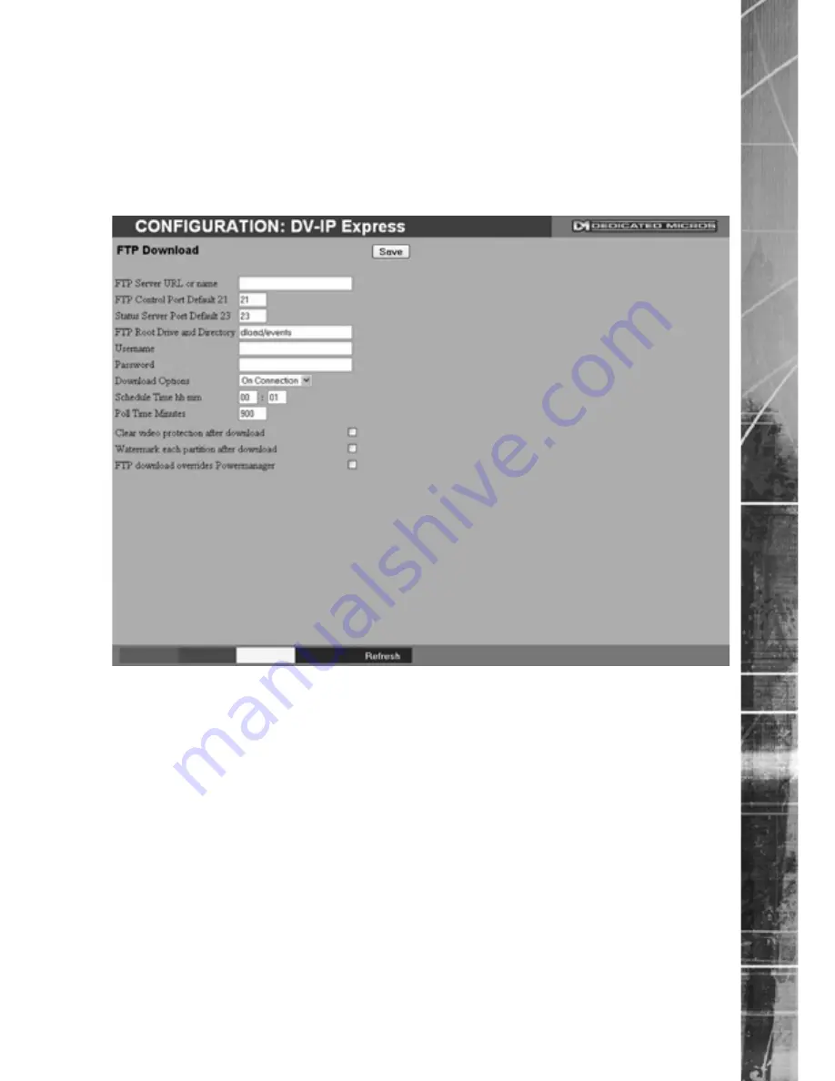
FTP Download
The unit can archive images to a central FTP (File Transfer Protocol) server. This could be on
receipt of an alarm, activation of the Activity Detection or at a scheduled time to backup recorded
video. Using FTP in a multi-unit application ensures that all files are stored in one central location for
each of the units, offering efficient file management and easy review capabilities.
Note:
This menu will only be displayed if ‘Automatic FTP Download’ is selected in the
System Settings:-Features menu.
FTP Server IP URL or name
This is the IP address, URL or name of the FTP server the
unit will connect to for FT� image download purposes.
FT� Control �ort Default 21
The default port for FT� use is port 21. �f this port has
already been allocated on the network, it is possible to
identify and allocate an alternati�e port.
Status Server Port Default 23
The default port for the Server Status function is port 23, if
this port has already been allocated on the network, it is
possible to identify and allocate an alternati�e port number.
FT� Root Dri�e and Directory
This is the directory where the images are to be stored, it is
recommended that a name associated with the unit be
used for ease of retrie�al.
Username
If it is necessary to use an authentication process to access
the FT� ser�er, enter the rele�ant username here.
�assword
�f it is necessary to use an authentication process to access
the FT� ser�er, enter the rele�ant password here.


